ВПУСКНОЙ КОЛЛЕКТОР УСТАНОВКА
PROCEDURE
-
INSTALL INTAKE MANIFOLD
-
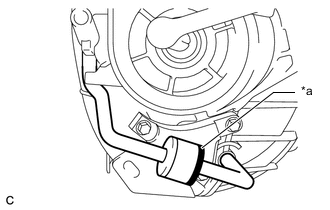
Install the wire harness clamp bracket to the intake manifold with the bolt.
- Torque:
- 10 N*m { 102 kgf*cm, 7 ft.*lbf }
-
*a Black Connect the 2 vacuum hoses and check that the No. 1 check valve is installed as shown in the illustration.
-
Check the 4 tumble control valves (TCV).
Note
The 4 tumble control valves (TCV) may be damaged if they are not closed before installing the intake manifold.
Tech Tips
Apply battery voltage to the terminals of the intake air control valve actuator (for TCV) to operate the motor and close the 4 tumble control valves (TCV).
-
Install a new intake manifold to head gasket to the intake manifold.
-
Temporarily install the intake manifold to the cylinder head sub-assembly with the 6 bolts.
-
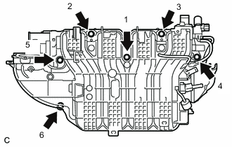
Tighten the 6 bolts in the order shown in the illustration.
- Torque:
- 21 N*m { 214 kgf*cm, 15 ft.*lbf }
-
Connect the intake air control valve actuator (for TCV) connector.
-
Engage the 2 wire harness clamps.
-
Connect the wire harness clamp bracket to the intake manifold with the bolt.
- Torque:
- 10 N*m { 102 kgf*cm, 7 ft.*lbf }
-
Connect the sensor wire connector.
-
Engage the 2 wire harness clamps.
-
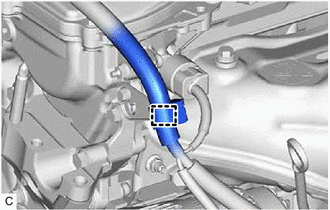
Connect the fuel vapor feed hose to the intake manifold and slide the clip to secure it.
-
-
INSTALL FUEL DELIVERY PIPE
-
CONNECT ENGINE WIRE
-
Engage the wire harness clamp and connect the engine wire.
-
Connect the 2 connectors and engage the wire harness clamp.
-
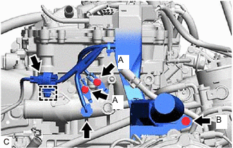
Install the engine wire to the cylinder head sub-assembly with the 2 bolts.
- Torque:
- Bolt (A)
- 8.35 N*m { 85 kgf*cm, 74 in.*lbf }
-
Install the engine wire to the wire harness clamp bracket with the bolt.
- Torque:
- Bolt (B)
- 7.65 N*m { 78 kgf*cm, 68 in.*lbf }
-
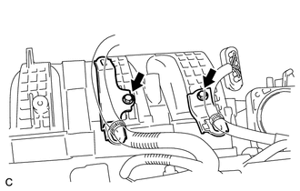
Install the 2 wire harness clamp brackets to the intake manifold with the 2 bolts.
- Torque:
- 10 N*m { 102 kgf*cm, 7 ft.*lbf }
-
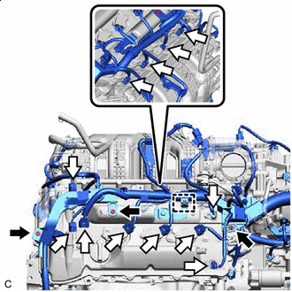

Nut 
Connector Connect the 12 connectors and engage the wire harness clamp.
-
Install the engine wire to the cylinder head cover sub-assembly with the 3 nuts.
- Torque:
- 7.65 N*m { 78 kgf*cm, 68 in.*lbf }
-
-
CONNECT FUEL TUBE SUB-ASSEMBLY
-
CONNECT UNION TO CHECK VALVE HOSE
-
Connect the union to check valve hose to the intake manifold and slide the clip to secure it.
-
-
CONNECT NO. 2 VENTILATION HOSE
-
Connect the No. 2 ventilation hose to the intake manifold and slide the clip to secure it.
-
-
INSTALL VACUUM SWITCHING VALVE ASSEMBLY (for ACIS)
-
Install the vacuum switching valve assembly (for ACIS) to the intake manifold with the bolt.
- Torque:
- 9.0 N*m { 92 kgf*cm, 80 in.*lbf }
-
Connect the vacuum switching valve assembly (for ACIS) connector.
-
Connect the 2 vacuum hoses.
-
Engage the wire harness clamp.
-
Connect the union to check valve hose to the vacuum hose clamp.
-
-
INSTALL THROTTLE BODY WITH MOTOR ASSEMBLY
-
INSTALL OUTER COWL TOP PANEL SUB-ASSEMBLY
-
INSTALL NO. 1 HEATER AIR DUCT SPLASH SHIELD SEAL
-
INSTALL NO. 2 HEATER AIR DUCT SPLASH SHIELD SEAL
-
INSTALL BRAKE MASTER CYLINDER RESERVOIR ASSEMBLY
-
INSTALL WINDSHIELD WIPER MOTOR AND LINK ASSEMBLY
-
INSPECT WASHER NOZZLE
-
CONNECT CABLE TO NEGATIVE BATTERY TERMINAL
Note
When disconnecting the cable, some systems need to be initialized after the cable is reconnected.
-
INSPECT FOR FUEL LEAK