TIRE PRESSURE WARNING SYSTEM, Diagnostic DTC:C2174/74, C2191/91
| DTC Code | DTC Name |
|---|---|
| C2174/74 | Vehicle Speed Signal Malfunction |
| C2191/91 | Vehicle Speed Signal Error (Test Mode DTC) |
DESCRIPTION
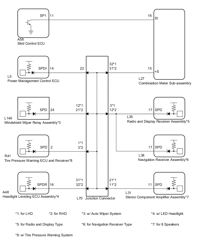
Speed signals are input into the tire pressure warning ECU and receiver from the combination meter assembly. At the same time, the acceleration sensor in the tire pressure warning valve and transmitter detects driving conditions, and sends signals to the tire pressure warning ECU and receiver. If the speed signal from the combination meter assembly stops and the acceleration sensor signal in the tire pressure warning valve and transmitter indicates that the vehicle is being driven, DTC C2174/74 is stored.
DTC C2191/91 is stored only during the test mode.
| DTC Code | Detection Condition | Trouble Area |
|---|---|---|
| C2174/74 | Vehicle speed signal malfunction |
|
| C2191/91 | Test mode procedure is performed |
|
WIRING DIAGRAM
CAUTION / NOTICE / HINT
Note
-
When replacing the tire pressure warning ECU and receiver, read the transmitter IDs stored in the old ECU using the GTS and write them down before removal.
-
It is necessary to perform initialization (See page ) after registration Click here of the transmitter IDs into the tire pressure warning ECU and receiver if the ECU and/or one of the valve and transmitters has been replaced.
Tech Tips
When the speedometer is not moving, first troubleshoot the meter / gauge system Click here.
PROCEDURE
-
READ VALUE USING DATA LIST (VEHICLE SPEED)
-
Turn the power switch off.
-
Connect the GTS to the DLC3.
-
Turn the power switch on (IG).
-
Turn the GTS on.
-
Enter the following menus: Chassis / Tire Pressure Monitor / Data List.
-
Check that the values indicated on the GTS and on the combination meter are the same.
Tire Pressure Monitor Tester Display Measurement Item/Range Normal Condition Diagnostic Note Vehicle Speed Vehicle speed reading/
min.: 0 km/h (0 mph)
max.: 255 km/h (158 mph)
Actual vehicle speed Speed indicated on the combination meter assembly OK Vehicle speed indicated on the GTS indicates the actual speed.
NG 
CHECK HARNESS AND CONNECTOR (TIRE PRESSURE WARNING ECU AND RECEIVER - JUNCTION CONNECTOR) Click here
OK 
-
-
CHECK DTC OUTPUT (C2174/74)
-
Perform a driving test.
-
Check for DTCs Click here.
Tech Tips
The time required for DTC C2174/74 to be stored is 20 minutes.
Result Result Proceed to DTC C2174/74 is not output A DTC C2174/74 is output B
A 
USE SIMULATION METHOD TO CHECK Click here
B
REPLACE TIRE PRESSURE WARNING ECU AND RECEIVER Click here
-
-
CHECK HARNESS AND CONNECTOR (TIRE PRESSURE WARNING ECU AND RECEIVER - JUNCTION CONNECTOR)
-
Disconnect the R41 tire pressure warning ECU and receiver connector.
-
Disconnect the L70 junction connector.
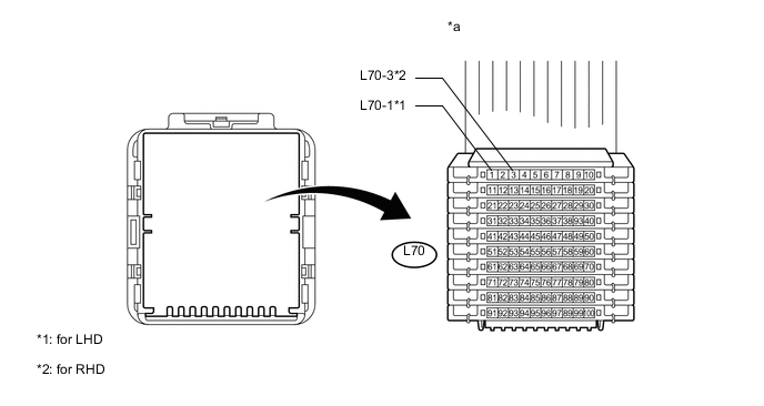
Text in Illustration *a Front view of wire harness connector
(to Junction Connector)
- - -
Measure the resistance according to the value(s) in the table below.
Standard Resistance for LHD Tester Connection Condition Specified Condition R41-2 (SPD) - L70-1 Always Below 1 Ω R41-2 (SPD) or L70-1 - Body ground Always 10 kΩ or higher for RHD Tester Connection Condition Specified Condition R41-2 (SPD) - L70-3 Always Below 1 Ω R41-2 (SPD) or L70-3 - Body ground Always 10 kΩ or higher
OK
GO TO SPEED SIGNAL CIRCUIT IN METER / GAUGE SYSTEM Click here
NG
REPAIR OR REPLACE HARNESS OR CONNECTOR
-
-
REPLACE TIRE PRESSURE WARNING ECU AND RECEIVER
-
Replace the tire pressure warning ECU and receiver Click here.
NEXT
-
-
REGISTRATION OF TRANSMITTER ID
-
Perform registration Click here.
NEXT
-
-
PERFORM INITIALIZATION
-
Perform initialization Click here.
NEXT
-
-
CHECK DTC OUTPUT (C2174/74)
-
Perform a driving test.
-
Check for DTCs Click here.
Tech Tips
The time required for DTC C2174/74 to be stored is 20 minutes.
Result Result Proceed to DTC C2174/74 is output A DTC C2174/74 is not output B
A
REPLACE TIRE PRESSURE WARNING VALVE AND TRANSMITTER Click here
B
END
-