БЛОК ДВИГАТЕЛЯ ПОВТОРНАЯ СБОРКА

-
INSTALL TIGHT PLUG
-
Apply adhesive to the end of new tight plugs.
Adhesive Toyota Genuine Adhesive 1324, Three Bond 1324 or equivalent Note
Do not start the engine for 1 hour after the installation.
-
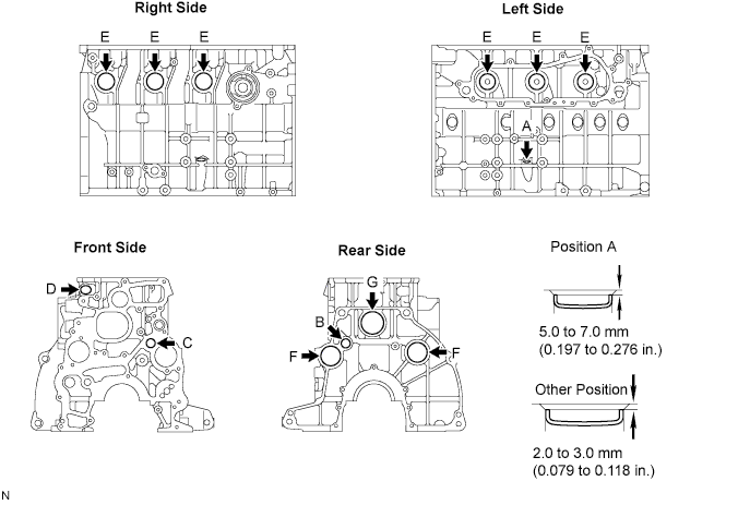
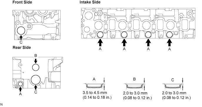
Using SST and a hammer, tap in the tight plugs as shown in the illustration.
-
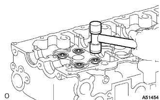
Position A:
Using 14 mm steel bar and a hammer, tap in the tight plug as shown in the illustration.
-
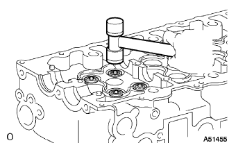
Other Positions:
Position B
- SST
- 09950-60010 ( 09951-00180 )
- 09950-70010 ( 09951-07100 )
Position C
- SST
- 09950-60010 ( 09951-00190 )
- 09950-70010 ( 09951-07100 )
Position D
- SST
- 09950-60010 ( 09951-00200 )
- 09950-70010 ( 09951-07100 )
Position E
- SST
- 09950-60010 ( 09951-00350 )
- 09950-70010 ( 09951-07100 )
Position F
- SST
- 09950-60010 ( 09951-00400 )
- 09950-70010 ( 09951-07100 )
Position G
- SST
- 09950-60010 ( 09951-00450 )
- 09950-70010 ( 09951-07100 )
-
-
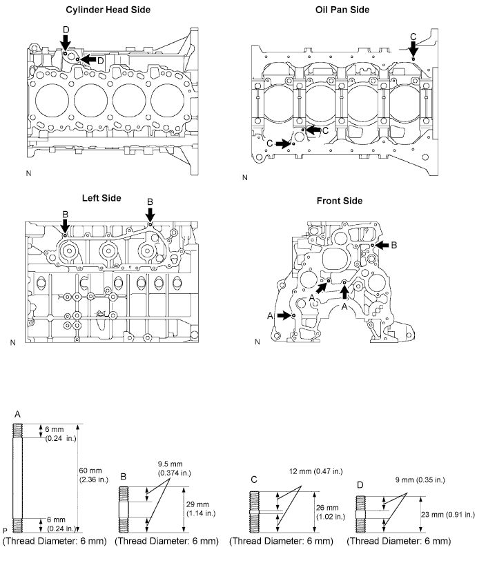
INSTALL END PLATE STRAIGHT PIN
-
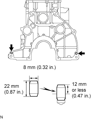
Install the end plate straight pins as shown in the illustration.
-
-
INSTALL ENGINE REAR OIL SEAL STRAIGHT PIN
-
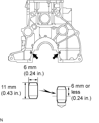
Install the engine rear oil seal straight pins as shown in the illustration.
-
-
INSTALL TIMING GEAR COVER SET STRAIGHT PIN
-
Install the timing gear cover set straight pins as shown in the illustration.
-
-
REMOVE CYLINDER HEAD SET RING PIN
-
Install the cylinder head set ring pins as shown in the illustration.
-
-
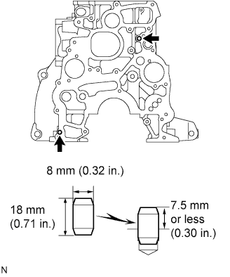
INSTALL STUD BOLT
-
Install the stud bolts as shown in the illustration.
- Torque:
- for A and B
- 7.0 N*m { 70 kgf*cm, 62 in.*lbf }
- Torque:
- for C
- 8.0 N*m { 80 kgf*cm, 71 in.*lbf }
- Torque:
- for D
- 4.0 N*m { 40 kgf*cm, 35 in.*lbf }
-
-
INSTALL PLUG
Note
If coolant leaks from the plug or the plug is corroded, replace the plug.
-
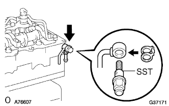
Clean the cylinder block side hole and plug with non-residue solvent.
-
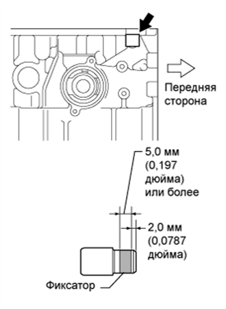
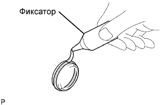
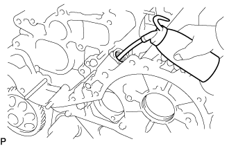
Apply adhesive onto the shaded area of the plug as shown in the illustration.
Adhesive Toyota Genuine Adhesive 1324, Three Bond 1324 or equivalent Note
Install the plug within 3 minutes after applying adhesive.
-
Set the plug and tap it until the edge of the plug fits against the chamfered part of the cylinder block as shown in the illustration.
-
-
INSTALL SCREW PLUG
-
Install a new gasket and the screw plug.
- Torque:
- 20 N*m { 204 kgf*cm, 15 ft.*lbf }
-
-
INSTALL OIL NOZZLE NO.1 SUB-ASSEMBLY
-
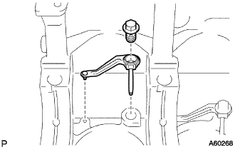
Align the pin of the oil nozzle with the pin hole of the cylinder block.
-
Install the oil nozzle with the check valve. Install the 4 oil nozzles and check valves.
- Torque:
- 26 N*m { 265 kgf*cm, 19 ft.*lbf }
-
-
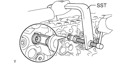
INSTALL CONNECTING ROD SMALL END BUSH
-
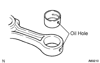
Align the oil holes of a new bush and the connecting rod.
-
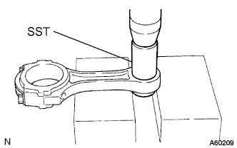
Using SST and a press, press in the bush.
- SST
- 09222-76012
-
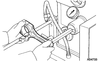
Using a pin hole grinder, hone the bush to obtain the standard specified clearance (see disassembly, step 85) between the bush and piston pin.
-
Check the piston pin fitting condition at normal room temperature.
-
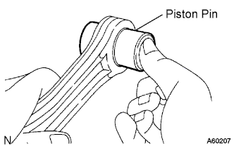
Coat the piston pin with engine oil, and push it into the connecting rod with your thumb.
-
-
-
INSTALL PISTON SUB-ASSEMBLY W/PIN
-
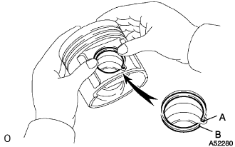
Using a screwdriver, install a new snap ring on one side of the piston hole.
Note
Install the snap ring so that either of snap ring ends A or B is aligned with the cutout on the piston.
-
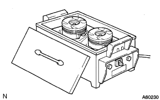
Gradually heat the piston to about 80°C (176°F).
-
Coat the piston pin with engine oil.
-
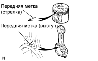
Align the front marks of the piston and connecting rod, and push in the piston pin with your thumb.
-
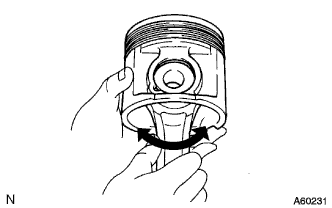
Check the fitting condition between the piston and piston pin. Try to move the piston back and forth on the piston pin.
-
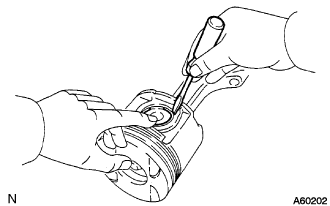
Using a screwdriver, install a new snap ring on the other side of the piston pin hole.
Tech Tips
Be sure that the end gap of the snap ring is not aligned with the pin hole cutout portion of the piston.
-
-
INSTALL PISTON RING SET
-
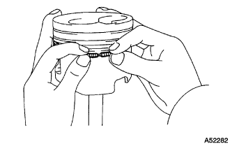
Install the oil ring coil by hand.
-
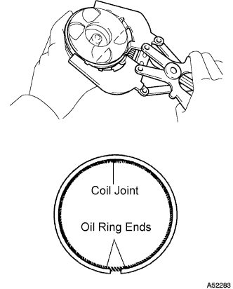
Using a piston ring expander, install the 2 oil rings.
-
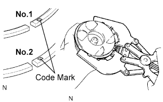
Using a piston ring expander, install the No.1 and No.2 piston rings with the code mark facing upward.
Code mark Ring Mark No.1 N No.2 NP -
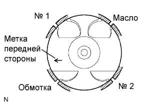
Position the piston rings so that the ring ends are as shown.
Note
Do not align the ring ends.
-
-
INSTALL CRANKSHAFT
Tech Tips
Upper bearings have an oil groove and oil hole. Lower bearings do not.
-
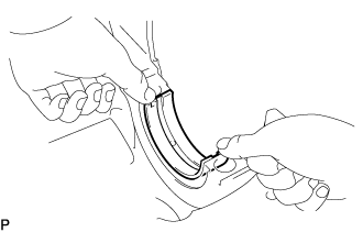
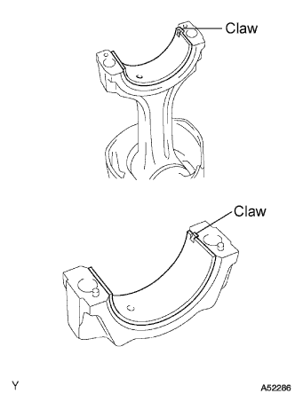
Align the bearing claw with the claw groove of the cylinder block, and push in the 5 upper bearings.
-
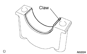
Align the bearing claw with the claw groove of the crankshaft bearing cap, and push in the 5 lower bearings.
-
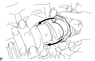
Place the crankshaft on the cylinder block.
-
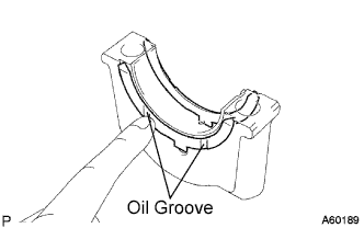
Install the 2 upper thrust washers to the No.5 journal position of the cylinder block.
-
Push the crankshaft toward the front (rear) side.
-
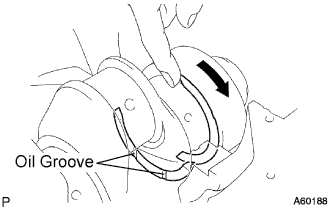
Install the 2 thrust washers with the oil grooves facing outward.
-
Install the 2 thrust washers on the No.5 bearing cap with the grooves facing outward.
-
Install the 5 crankshaft bearing caps in their proper locations.
-
Install the crankshaft bearing cap bolts.
Tech Tips
-
The main bearing cap bolts are tightened in 2 progressive steps (steps [*1] and [*2]).
-
If a main bearing cap bolt is broken or deformed, replace it.
-
Apply a light coat of the engine oil to the threads and under the bolt heads of the main bearing caps.
-
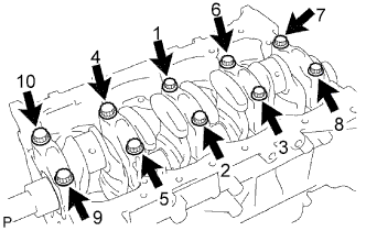
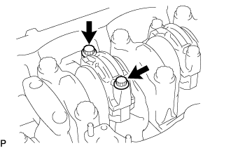
Install and uniformly tighten the 10 bolts of the main bearing caps in several steps in the sequence shown in the illustration. [*1]
- Torque:
- 50 N*m { 510 kgf*cm, 37 ft.*lbf }
If any one of the bearing cap bolts does not meet the torque specification, replace the bearing cap bolt.
-
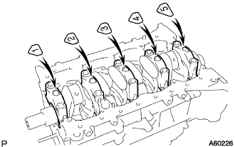
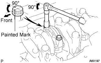
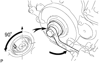
Mark the front of the main bearing cap bolt with paint.
-
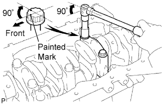
Retighten the main bearing cap bolts 90° in the numerical order shown above. [*2]
-
Check that the painted mark is now at a 90° angle to the front.
-
-
Check that the crankshaft turns smoothly.
-
Check the crankshaft thrust clearance (see disassembly, step 73).
-
-
INSTALL CONNECTING ROD SUB-ASSEMBLY
-
Align the bearing claw with the groove of the connecting rod or connecting cap.
-
Install the bearings in the connecting rod and connecting rod cap.
-
Position the piston rings so that the ring ends are as shown.
-
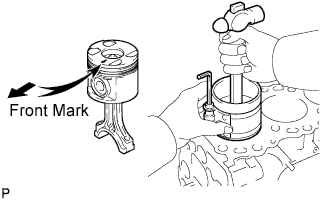
Using a piston ring compressor, push the correctly numbered piston and connecting rod assembly into the cylinder with the front mark of the piston facing forward.
-
Place the connecting rod cap on the connecting rod.
-
Match the numbered connecting rod cap with the connecting rod.
-
Align the pins of the connecting rod cap with the pin holes of the connecting rod, and install the connecting rod cap.
-
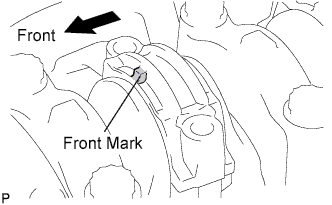
Check that the front mark of the connecting rod cap is facing forward.
-
-
Install the connecting rod cap bolts.
Tech Tips
The connecting rod cap bolts are tightened in 2 progressive steps (steps [*1] and [*2]).
If any connecting rod bolt is broken or deformed, replace it.
-
Apply a light of engine oil to the threads and under the heads of the connecting rod cap bolts.
-
Install and alternately tighten the bolts of the connecting rod cap in several steps. [*1]
- Torque:
- 35 N*m { 357 kgf*cm, 26 ft.*lbf }
Tech Tips
If any one of the connecting rod cap bolts does not meet the torque specification, replace the cap bolts.
-
Mark the front of the connecting rod cap bolts with paint.
-
Retighten the connecting rod cap bolts 90° as shown. [*2]
-
Check that the painted mark is now at a 90° angle to the front.
-
-
Check that the crankshaft turns smoothly.
-
Check the connecting rod thrust clearance (see disassembly, step 67).
-
-
INSTALL CYLINDER BLOCK OIL ORIFICE
-
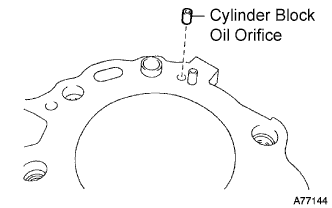
Install the cylinder block oil orifice to the cylinder block.
-
-
INSTALL TIGHT PLUG
-
Apply adhesive to new tight plugs.
Adhesive Toyota Genuine Adhesive 1324, Three Bond 1324 or equivalent -
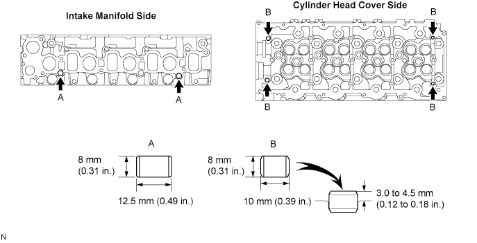
Using SST and a hammer, tap in the tight plugs as shown in the illustration.
-
Position A
- SST
- 09950-60010 ( 09951-00200 )
- 09950-70010 ( 09951-07100 )
-
Position B
- SST
- 09950-60010 ( 09951-00300 )
- 09950-70010 ( 09951-07100 )
-
Position C
- SST
- 09950-60010 ( 09951-00350 )
- 09950-70010 ( 09951-07100 )
-
-
-
INSTALL RING PIN
-
Install the ring pins as shown in the illustration.
-
-
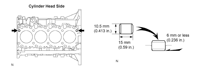
INSTALL STUD BOLT
-
Install the stud bolts as shown in the illustration.
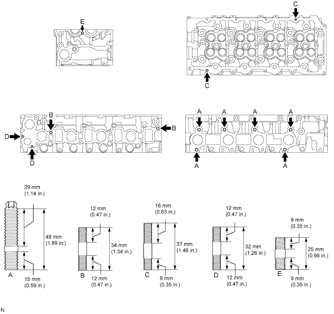
- Torque:
- for A (Thread Diameter 10 mm)
- 26 N*m { 265 kgf*cm, 19 ft.*lbf }
- Torque:
- for B (Thread diameter 8 mm)
- 15 N*m { 150 kgf*cm, 11 ft.*lbf }
- Torque:
- for C (Thread diameter 6 mm)
- 5.0 N*m { 50 kgf*cm, 44 in.*lbf }
- Torque:
- for D (Thread diameter 6 mm)
- 7.0 N*m { 70 kgf*cm, 62 in.*lbf }
- Torque:
- for E (Thread diameter 6 mm)
- 5.0 N*m { 50 kgf*cm, 44 in.*lbf }
-
-
INSTALL STRAIGHT SCREW PLUG NO.1
-
Apply adhesive to the end of the screw plug.
Adhesive Toyota Genuine Adhesive 1324, Three Bond 1324 or equivalent -
Using a 6 mm hexagon wrench, install the screw plug.
- Torque:
- 25 N*m { 255 kgf*cm, 18 ft.*lbf }
-
-
INSTALL SEMICIRCULAR PLUG
-
Remove any old packing (FIPG) material.
-
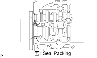
Apply seal packing to the oil seal retainer as shown in the illustration.
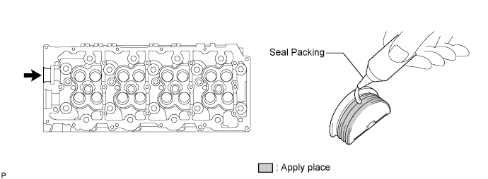
Seal packing Toyota Genuine Seal Packing Black, Three Bond 1207B or equivalent Note
-
The semicircular plug must be installed within 3 minutes after the completion of applying the seal packing.
-
Prevent FIPG from being stuck to the camshaft thrust groove.
-
-
Install the semicircular plug to the cylinder head.
-
-
INSTALL VALVE SPRING SEAT PLATE WASHER
-
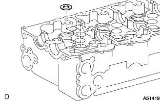
Install the valve spring seat plate washers to the cylinder head.
-
-
INSTALL VALVE STEM OIL SEAL
-
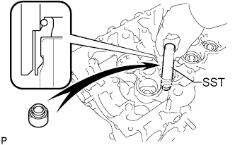
Using SST, push in a new oil seal.
- SST
- 09201-41020
-
-
INSTALL INTAKE VALVE
-
Apply plenty of engine oil to the valve stem tip.
-
Install the valve, spring seat, compression spring and spring retainer.
-
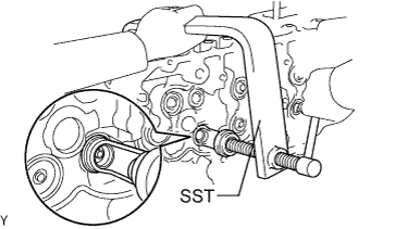
Using SST, compress the compression spring and place the 2 keepers around the valve stem.
- SST
- 09202-70020 ( 09202-00020 )
-
Using a plastic hammer, lightly tap the valve stem tip to assure a proper fit.
Note
Do not damage the valve stem tip.
-
-
INSTALL EXHAUST VALVE
-
Apply plenty of engine oil to the valve stem tip.
-
Install the valve, spring seat, compression spring and spring retainer.
-
Using SST, compress the compression spring and place the 2 keepers around the valve stem.
- SST
- 09202-70020 ( 09202-00020 )
-
Using a plastic hammer, lightly tap the valve stem tip to assure a proper fit.
Note
Do not damage the valve stem tip.
-
-
INSTALL VALVE LIFTER
-
Apply plenty of engine oil to the valve lifters.
-
Install the valve lifters.
-
Check that the valve lifter rotates smoothly by hand.
-
-
INSTALL SUPPLY PUMP GEAR BEARING
-
Using SST and a press, press in a new bearing.
- SST
- 09223-00010
- 09223-15020
- 09502-12010
- 09950-70010 ( 09951-07100 )
-
-
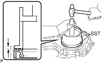
INSTALL ENGINE REAR OIL SEAL
-
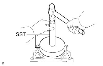
Using SST and a hammer, tap in a new oil seal until its surface is flush with the rear oil seal retainer edge.
- SST
- 09518-36030
- 09950-70010 ( 09951-07200 )
Oil seal depth from the flat-end surface 0 to -0.5 mm (0 to -0.020 in.) -
Apply MP grease to the oil seal lip.
Note
Keep the lip clean. Prevent dirt and dust from adhering to that area.
-
-
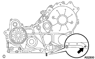
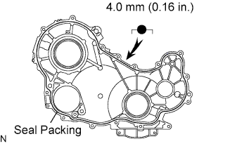
INSTALL ENGINE REAR OIL SEAL RETAINER
-
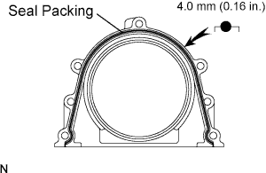
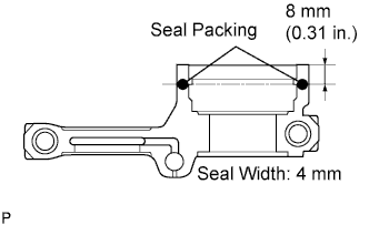
Apply seal packing to the specific places described in the illustration.
Seal packing Toyota Genuine Seal Packing Black, Three Bond 1207B or equivalent Seal width 4.0 mm (0.16 in.) Note
After applying FIPG, install the engine rear oil seal retainer within 3 minutes and tighten its bolts within 15 minutes.
-
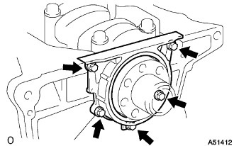
Install the retainer with the 5 bolts.
- Torque:
- 13 N*m { 133 kgf*cm, 10 ft.*lbf }
-
-
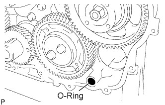
INSTALL TIMING GEAR CASE ASSEMBLY
-
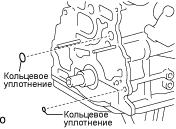
Install 2 new O-rings to the cylinder block grooves.
-
Install the stud bolt.
- Torque:
- 8.0 N*m { 82 kgf*cm, 71 in.*lbf }
-
Remove any old packing (FIPG) material.
-
Install the oil pump rotor to the timing gear case.
-
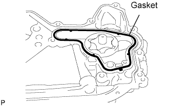
Install a new gasket to the groove of the timing gear case.
-
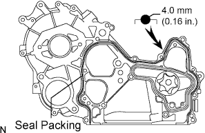
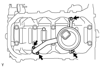
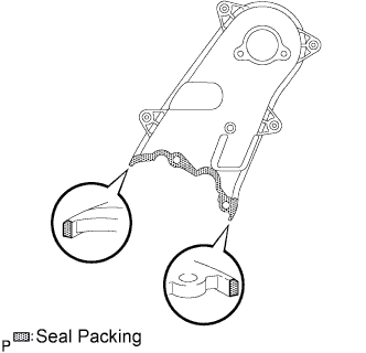
Apply seal packing to the timing gear case as shown in the illustration.
Seal packing Toyota Genuine Seal Packing Black, Three Bond 1207B or equivalent Seal width 4.0 mm (0.16 in.) Note
Install the timing gear case assembly within 3 minutes and tighten its bolts within 15 minutes after applying FIPG is competed.
-
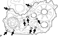
Install the timing gear case with the union bolt and 8 bolts.
- Torque:
- 16 N*m { 163 kgf*cm, 12 ft.*lbf, for union bolt (A) }
- 13 N*m { 133 kgf*cm, 10 ft.*lbf, for other bolts }
-
Remove the screw plug.
-
Pour approximately 50 cc (1.7 fl.oz) of engine oil into the oil pump.
-
Reinstall a new gasket and the screw plug.
- Torque:
- 42 N*m { 423 kgf*cm, 31 ft.*lbf }
-
-
INSTALL OIL STRAINER SUB-ASSEMBLY
-
Install a new gasket and the oil strainer with the 2 bolts and 2 nuts.
- Torque:
- 8.0 N*m { 82 kgf*cm, 71 in.*lbf }
-
-
INSTALL OIL PAN SUB-ASSEMBLY
-
Remove any old packing (FIPG) material.
-
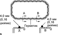
Apply seal packing to the oil pan as shown in the illustration.
Seal packing Toyota Genuine Seal Packing Black, Three Bond 1207B or equivalent Seal width 4.0 mm (0.16 in.) Note
Install the oil pan assembly within 3 minutes and tighten its bolts within 15 minutes after applying FIPG is competed.
-
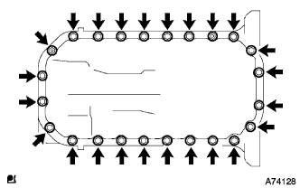
Install the oil pan with the 22 bolts and 2 nuts.
- Torque:
- 16 N*m { 163 kgf*cm, 12 ft.*lbf }
-
Install a new gasket and the drain plug.
- Torque:
- 34 N*m { 347 kgf*cm, 25 ft.*lbf }
-
-
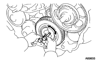
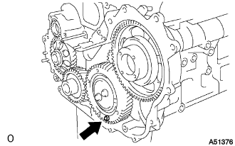
INSTALL SUPPLY PUMP GEAR
-
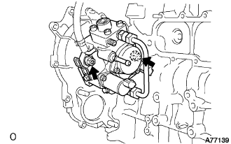
Install the supply pump with the 2 nuts.
- Torque:
- 21 N*m { 214 kgf*cm, 15 ft.*lbf }
-
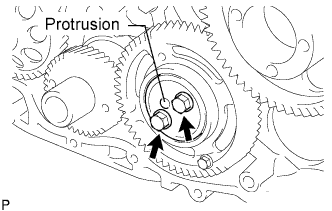
Temporarily install the O-ring and supply pump gear with the nut.
Tech Tips
Fit the key (protrusion) of the supply pump to the key slot of the supply pump gear.
-
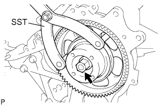
Using SST, tighten the nut.
- SST
- 09960-10010 ( 09962-01000, 09963-01000 )
- Torque:
- 64 N*m { 653 kgf*cm, 47 ft.*lbf }
-
-
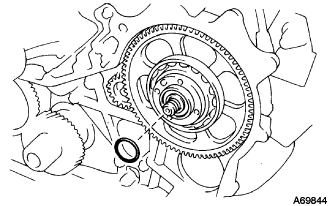
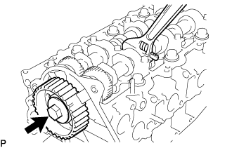
INSTALL CRANKSHAFT TIMING GEAR
-
Face the crankshaft timing gear with timing mark 1 facing forward.
-
Align the set key on the crankshaft with the key groove of the crankshaft timing gear.
-
Using SST and a hammer, tap in the timing gear.
- SST
- 09223-00010
-
-
INSTALL IDLE GEAR SHAFT NO.1
-
Coat the idle gear shaft No.1 with engine oil as shown in the illustration.
-
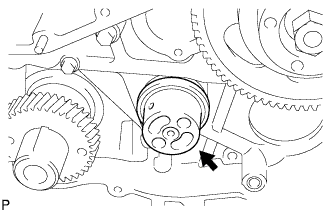
Install the gear shaft.
-
-
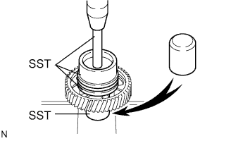
INSTALL IDLE SUB GEAR NO.2
-
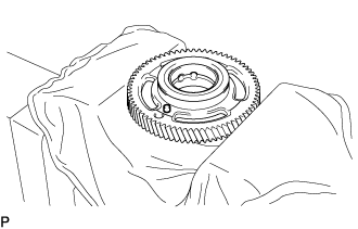
Mount the idler gear No.1 in a vise as shown in the illustration.
Note
Do not damage the gear.
-
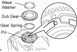
Install the gear spring.
-
Install the sub gear No.2.
Tech Tips
Align the pins on the gears with the spring ends.
-
Install the wave washer.
-
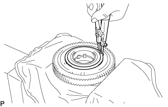
Using snap ring pliers, install the snap ring.
-
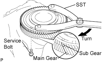
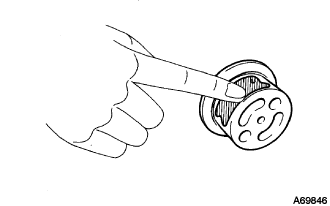
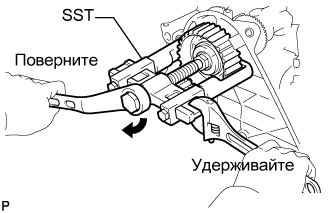
Using SST, align the holes of the idler main gear and sub gears by turning the sub gear clockwise, and install a service bolt.
- Torque:
- 8.0 N*m { 82 kgf*cm, 71 in.*lbf }
- SST
- 09960-10010 ( 09962-01000, 09963-00600 )
Tech Tips
Align the gear teeth of the main gear and sub gear, and tighten the service bolt.
Recommended service bolt: Thread diameter 6 mm Thread pitch 1.0 mm Bolt length Approx. 28 mm (1.1 in.)
-
-
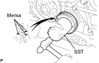
INSTALL IDLE GEAR NO.1
-
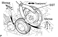
Align the "5" timing marks of the idle gear and crankshaft timing gear.
-
Using SST, turn the supply pump gear, and align the "4" timing marks of the idle gear and supply pump gear, and mesh the gears.
- SST
- 09960-10010 ( 09962-01000, 09963-00600 )
-
-
INSTALL CRANKSHAFT POSITION SENSOR PLATE NO.1
-
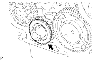
Align the set key with the key groove of the sensor plate.
-
Install the sensor plate with the cup side facing outward.
-
-
INSTALL IDLE GEAR THRUST PLATE
-
Face the thrust plate with the protrusion facing outward.
-
Align the bolt holes, and install the thrust plate with the 2 bolts.
- Torque:
- 50 N*m { 510 kgf*cm, 37 ft.*lbf }
-
-
INSTALL TIMING GEAR CASE OR TIMING CHAIN CASE OIL SEAL
-
Using SST and a hammer, tap in a new oil seal until its surface is flush with the timing gear cover edge.
- SST
- 09608-32010
- 09950-70010 ( 09951-07100 )
Oil seal depth from the flat-end surface 0 to -0.5 mm (0 to -0.020 in.) -
Apply MP grease to the oil seal lip.
Note
Keep the lip clean. Prevent dirt and dust from adhering to that area.
-
-
INSTALL TIMING CHAIN OR BELT COVER OIL SEAL
-
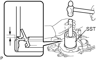
Using SST and a hammer, tap in a new oil seal until its surface is flush with the timing gear cover edge.
- SST
- 09649-17010
- 09950-70010 ( 09951-07100 )
Oil seal depth from the flat-end surface 0 to -0.5 mm (0 to -0.020 in.) -
Apply MP grease to the oil seal lip.
Note
Keep the lip clean. Prevent dirt and dust from adhering to that area.
-
-
INSTALL TIMING GEAR CASE
-
Remove the service bolt.
-
Install a new O-ring to the timing gear case assembly.
-
Apply seal packing to the timing gear case as shown in the illustration.
Seal packing Toyota Genuine Seal Packing Black, Three Bond 1207B or equivalent Seal width 4.0 mm (0.16 in.) Note
Install the timing gear case within 3 minutes and tighten its bolts within 15 minutes after applying FIPG is competed.
-
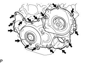
Install the timing gear case with the 14 bolts and 2 nuts.
- Torque:
- 13 N*m { 133 kgf*cm, 10 ft.*lbf }
-
-
INSTALL WATER PUMP ASSEMBLY
-
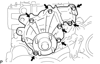
Install a new gasket and the water pump with the 5 bolts and 2 nuts.
- Torque:
- 13 N*m { 133 kgf*cm, 10 ft.*lbf }
-
-
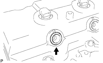
INSTALL CYLINDER HEAD SUB-ASSEMBLY
-
Check the piston protrusions for each cylinder.
-
Clean the cylinder block with solvent.
-
Set the piston of the cylinder to be measured to slightly before TDC.
-
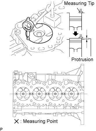
Place a dial indicator on the cylinder block, and set the measuring tip as shown in the illustration.
-
Set the dial indicator at 0 mm (0 in.).
Tech Tips
Make sure that the measuring tip is square to the cylinder block gasket surface and piston head when taking the measurements.
-
Find where the piston head protrudes most by slowly turning the crankshaft clockwise and counterclockwise.
-
Measure each cylinder at 2 places as shown in the illustration, making a total of 8 measurements.
-
For the piston protrusion value of each cylinder, use the average of the 2 measurements of each cylinder.
Tech Tips
If the protrusion is not as specified, remove the piston and connecting rod assembly and reinstall it.
Piston protrusion 0.005 to 0.254 mm (0.0002 to 0.0100 in.)
-
-
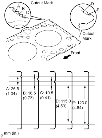
Select a new cylinder head gasket.
Tech Tips
Cylinder head gaskets are marked A, B, C, D or E accordingly.
New installed cylinder head gasket thickness Cutout mark Thickness A 0.80 to 0.90 mm (0.0315 to 0.0354 in.) B 0.85 to 0.95 mm (0.0335 to 0.0374 in.) C 0.90 to 1.00 mm (0.0354 to 0.0394 in.) D 0.95 to 1.05 mm (0.0374 to 0.0413 in.) E 1.00 to 1.10 mm (0.0394 to 0.0433 in.)
-
Select the largest piston protrusion value from the measurements made and then select a new appropriate gasket according to the table below.
Piston protrusion Gasket size 0.005 to 0.054 mm (0.0002 to 0.0021 in.) Use A 0.055 to 0.104 mm (0.0022 to 0.0041 in.) Use B 0.105 to 0.154 mm (0.0041 to 0.0061 in.) Use C 0.155 to 0.204 mm (0.0061 to 0.0080 in.) Use D 0.205 to 0.254 mm (0.0081 to 0.0100 in.) Use E
-
-
Using the crankshaft pulley bolt, set the No. 1 cylinder to 90° BTDC/compression.
-
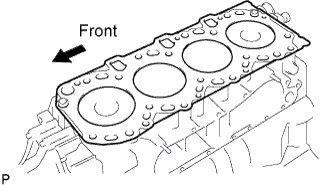
Place the cylinder head gasket in position on the cylinder block.
-
Place the cylinder head on the cylinder block.
Note
Be careful of the installation direction.
-
Install the cylinder head bolts.
Tech Tips
-
The cylinder head bolts are tightened in 3 progressive steps (steps [*1], [*2] and [*3]).
-
If any bolts is broken or deformed, replace it.
-
Apply a light coat of engine oil to the threads and under the heads of the cylinder head bolts.
-
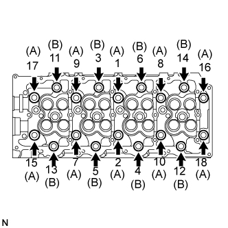
Install and uniformly tighten the 18 cylinder head bolts, in several steps in the sequence shown in the illustration. [*1]
- Torque:
- 85 N*m { 867 kgf*cm, 63 ft.*lbf }
Bolt length 110 mm (4.33 in.) for A 167 mm (6.57 in.) for B If any one of the cylinder head bolts does not meet the torque specification, replace the cylinder head bolt.
-
-
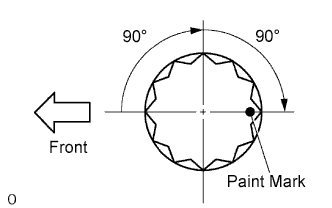
Mark the front of the cylinder head bolt with paint.
-
Retighten the cylinder head bolts by 90° in the sequence shown in the illustration. [*2]
-
Retighten the cylinder head bolts by an additional 90°. [*3]
-
Check that the painted mark is now facing rearward.
-
-
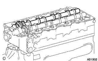
INSTALL CAMSHAFT
-
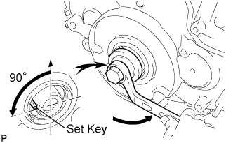
Using the crankshaft pulley bolt, set the No. 1 cylinder to 90° BTDC/compression.
Tech Tips
Set the No. 1 cylinder to 90° BTDC/compression to avoid interference with the piston top and valve head.
-
Install the camshaft.
-
Apply MP grease to the thrust portion of the camshafts.
-
Place the camshaft on the cylinder head and face the key groove upward.
-
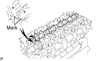
Align the timing marks (1 dot mark) of the camshaft drive and driven main gears, and place the No. 2 camshaft.
-
Install the 5 bearing caps in their proper locations.
-
Apply a light coat of engine oil to the threads and under the heads of the bearing cap bolts.
-
Install and uniformly tighten the 10 bearing cap bolts, in several steps in the sequence shown.
- Torque:
- 19 N*m { 194 kgf*cm, 14 ft.*lbf }
-
-
-
INSTALL TIMING BELT NO.2 COVER
-
Install the timing belt No. 2 cover with the 4 bolts and nut.
- Torque:
- 10 N*m { 102 kgf*cm, 7 ft.*lbf }
-
-
INSTALL CAMSHAFT TIMING PULLEY
-
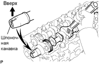
Install the set key to the key groove of the camshaft.
-
Align the set key with the key groove of the timing pulley.
-
Hold the hexagon portion of the camshaft, and install the timing pulley with the bolt.
- Torque:
- 98 N*m { 1,000 kgf*cm, 72 ft.*lbf }
-
-
INSPECT VALVE CLEARANCE
-
Inspect the valve clearance.
-
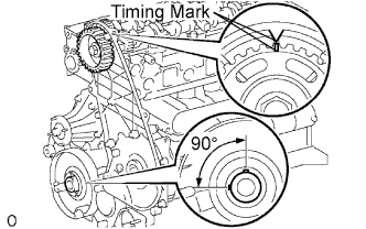
Lower the piston by rotating the crankshaft about 90° counterclockwise from the TDC position.
-
Align the timing mark of the camshaft timing pulley with the arrow mark of the timing belt No.2 cover.
-
Using a feeler gauge, measure the clearance between the valve lifter and camshaft.
Valve clearance (cold) Clearance Intake 0.20 to 0.30 mm (0.0079 to 0.0118 in.) Exhaust 0.35 to 0.45 mm (0.0138 to 0.0177 in.) -
Record the out-of-specification valve clearance measurements. They will be used later to determine the required replacement valve lifter.
-
-
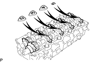
Turn the camshaft 1/2 revolutions (180°).
-
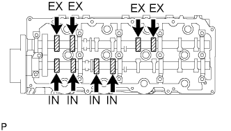
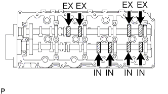
Check only the valves indicated in the illustration. Measure the valve clearance (see procedure (a) above).
-
-
REMOVE CAMSHAFT TIMING PULLEY
-
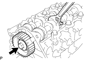
Remove the bolt for the camshaft timing pulley by holding the camshaft with a wrench.
-
Using SST, remove the camshaft timing pulley and set key.
- SST
- 09950-40011 ( 09951-04010, 09952-04010, 09953-05010, 09957-04010 )
- 09955-04150
-

Rotate the crankshaft about 90° counterclockwise from the TDC position to lower the piston.
-
-
REMOVE TIMING BELT NO.2 COVER
-
Remove the nut, 4 bolts and timing belt No.2 cover.
-
-
REMOVE NO.2 CAMSHAFT
-
Face the key groove of the camshaft upward by turning the camshaft with a wrench.
-
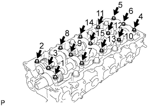
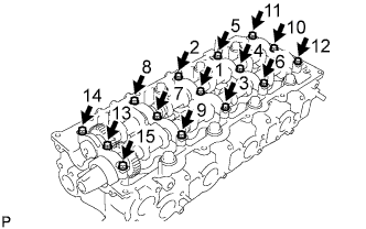
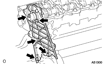
Uniformly loosen the 15 bearing cap bolts in several steps in the sequence shown in the illustration.
-
Remove the 5 bearing caps.
-
Remove the No.2 camshaft.
-
-
REMOVE CAMSHAFT
-
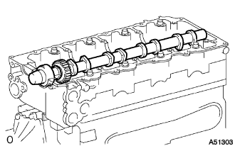
Remove the camshaft.
-
-
ADJUST VALVE CLEARANCE
-
Adjust the valve clearance.
Tech Tips
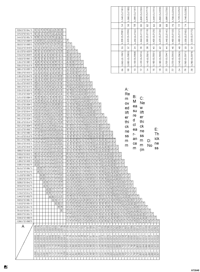
Determine the replacement valve lifter size according to the chart and formula:
-
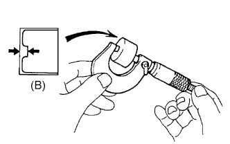
Using a micrometer, measure the thickness of the removed lifter.
-
Calculate the thickness of a new lifter so the valve clearance comes within the specified value.
A Thickness of new lifter B Thickness of used lifter C Measured valve clearance Valve clearance Intake A = B + (C -0.25 mm (0.0098 in.)) Exhaust A = B+ (C -0.40 mm (0.0158 in.)) -
Select a new lifter with a thickness as close as possible to the calculated values.
Tech Tips
Valve lifters are available in 35 sized in increments of 0.020 mm (0.0008 in.), from 5.060 mm (0.1992 in.) to 5.740 mm (0.2260 in.).
-
-
Valve lifter selection chart (Intake).
Tech Tips
EXAMPLE: The 5.250mm (0.2067 in.) lifter is installed, and the measured clearance is 0.400 mm (0.0158 in.). Replace the 5.250 mm (0.2067 in.) shim with a new No. 40 lifter.
Intake valve clearance (Cold) 0.20 to 0.30 mm (0.0079 to 0.0118 in.) -
Valve lifter selection chart (Exhaust).
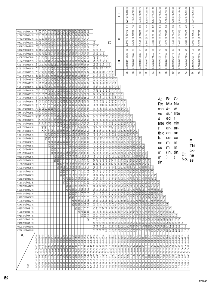
Tech Tips
EXAMPLE: The 5.340mm (0.2102 in.) lifter is installed, and the measured clearance is 0.480 mm (0.0189 in.). Replace the 5.340 mm (0.2102 in.) shim with a new No. 42 lifter.
Exhaust valve clearance (Cold) 0.35 to 0.45 mm (0.0138 to 0.00177 in.) -
Install the selected valve lifter.
-
-
INSTALL CAMSHAFT
-
Using the crankshaft pulley bolt, set the No. 1 cylinder to 90° BTDC/compression.
Tech Tips
Set the No. 1 cylinder to 90° BTDC/compression to avoid interference with the piston top and valve head.
-
Install the camshaft.
-
Apply MP grease to the thrust portion of the camshafts.
-
Place the camshaft on the cylinder head and face the key groove upward.
-
Align the timing marks (1 dot mark) of the camshaft drive and driven main gears, and place the No. 2 camshaft.
-
Apply seal packing to the No. 1 bearing cap.
Seal packing Toyota Genuine Seal Packing Black, Three Bond 1207B or equivalent Seal width 4 mm (0.16 in.) Note
-
Beware that FIPG does not stick to the oil passage of the bearing cap.
-
Once completed applying FIPG, install the camshaft bearing cap within 3 minutes and fasten its bolts within 15 minutes.
-
Do not start the engine for 2 hours after the installation.
-
-
Install the 5 bearing caps in their proper locations.
-
Apply a light coat of engine oil to the threads and under the heads of the bearing cap bolts.
-
Install and uniformly tighten the 10 bearing cap bolts, in several steps in the sequence shown.
- Torque:
- 19 N*m { 194 kgf*cm, 14 ft.*lbf }
-
-
-
INSTALL CAMSHAFT SETTING OIL SEAL
-
Install the camshaft oil seal.
-
Apply MP grease to a new oil seal lip.
Note
Keep the lip free from foreign objects.
-
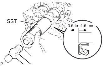
Using SST and a hammer, tap in the oil seal until its surface is flush with the cylinder head edge.
- SST
- 09608-06041
Oil seal depth from the flat-end surface 0.5 to -1.5 mm (0.020 to -0.059 in.)
-
-
-
INSTALL TIMING BELT NO.2 COVER
-
Apply seal packing to the timing gear cover as shown in the illustration.
Seal packing Toyota Genuine Seal Packing Black, Three Bond 1207B or equivalent Note
Install the timing belt No. 2 cover within 3 minutes and tighten its bolts and nut within 15 minutes after applying FIPG is competed.
-
Install the timing belt No. 2 cover with the 4 bolts and nut.
- Torque:
- 10 N*m { 102 kgf*cm, 7 ft.*lbf }
-
-
INSTALL CAMSHAFT TIMING PULLEY
-
Install the set key to the key groove of the camshaft.
-
Align the set key with the key groove of the timing pulley.
-
Hold the hexagon portion of the camshaft, and install the timing pulley with the bolt.
- Torque:
- 98 N*m { 1,000 kgf*cm, 72 ft.*lbf }
-
-
INSTALL INJECTOR ASSEMBLY
-
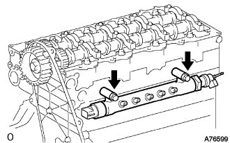
Install the common rail with the 2 bolts.
- Torque:
- 38 N*m { 387 kgf*cm, 28 ft.*lbf }
-
Install 4 new injection nozzle sheets to the cylinder head.
-
Apply a light coat of clean engine oil to new O-rings.
-
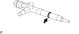
Install the O-ring to each injector as shown in the illustration.
-
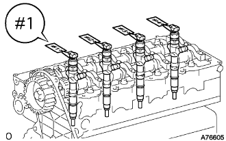
Insert the 4 injectors into the cylinder head.
Note
-
At this time, insert the injector until it touches the nozzle sheet surface.
-
After installing the injector to the cylinder head, the O-ring may prevent the injector from fully seating. If so, pull out the injector and reinstall it again.
-
Always return an injector to the same place it was removed from.
-
-
Check the nozzle leakage pipe. Check that there are no scratches or dents on the 5 union seal surfaces.
Tech Tips
If scratches or dents are present, replace the nozzle leakage pipe.
-
Install the nozzle leakage pipe and 5 new gaskets.
-
Apply a light coat of oil onto the 4 hollow screws and union bolt.
-
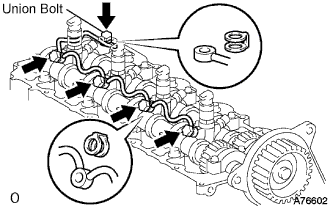
Temporarily install the nozzle leakage pipe with the 4 hollow screws and union bolt.
Note
Make sure that the injector hollow screw and union bolt are not deformed or damaged.
-
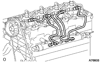
Temporarily install the 4 injection pipes.
Note
For positioning the injectors, loosely tighten the union nut.
-
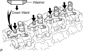
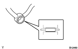
Set the holder clamps to each injector as shown in the illustration.
-
Set new washers on the nozzle holder clamps as shown in the illustration.
-
Tighten the bolts.
- Torque:
- 22 N*m { 224 kgf*cm, 16 ft.*lbf }
Note
-
The fork portion of the nozzle holder clamp must be set in the groove of the injector, not other portion.
-
Before tightening the bolts, check that the nozzle holder clamp is set properly.
-
To fasten the clamp bolts, temporarily tighten them by hand until they cannot turn. Then, tighten the bolts to specified torque.
-
When tightening to a specified torque, pay attention not to tilt the bolt and the clamp.
-
The washer cannot be reused.
-
If the nozzle leakage pipe is accidentally tightened beyond the torque specification, it must be replaced.
-
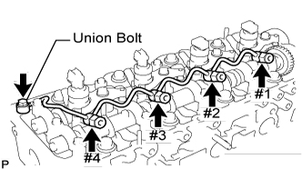
Tighten the 4 hollow screws from #1 and #4 in order.
- Torque:
- 16 N*m { 163 kgf*cm, 12 ft.*lbf }
Note
If any of the screws are overtightened, replace the nozzle leakage pipe with a new one.
-
Tighten the union bolt.
- Torque:
- 13 N*m { 130 kgf*cm, 9 ft.*lbf }
Note
If the bolt is overtightened, replace the nozzle leakage pipe with a new one.
-
Remove the 4 injection pipes.
-
Check that there are no leaks from the nozzle leakage pipe connection.
-
Using SST, install the nozzle leakage pipe No.2 and new gasket to the cylinder head.
- SST
- 09280-00010
- Torque:
- 21 N*m { 215 kgf*cm, 15 ft.*lbf }
Tech Tips
Nozzle leakage pipe No. 2: Part No. 23762-27010
-
Apply a light coat of soapy water (any fluid to detect fuel leakage) to the nozzle leakage pipe connection.
-
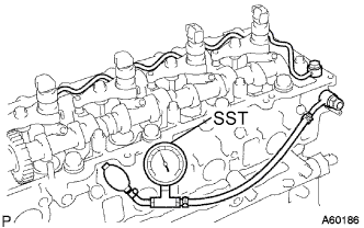
Using SST (turbocharger pressure gauge), apply SST to the fuel return side of the leakage pipe, and maintain 250 kPa (2.5 kgf*cm2, 35.5 psi) of pressure for 60 seconds to check that no bubbles come out.
- SST
- 09992-00242
Note
Be sure to keep specified pressure, preventing from leakage.
Tech Tips
-
Apply a coat of engine oil to the leakage pipe connection, and check that no bubbles come from the leakage pipe connection or each nozzle leakage pipe connection.
-
Check that the indication on the SST (turbo charger pressure gauge) does not go down while pressure is applied.
-
Remove the SST, union bolt, bolt and nozzle leakage pipe No.2.
-
-
-
INSTALL CYLINDER HEAD COVER SUB-ASSEMBLY
-
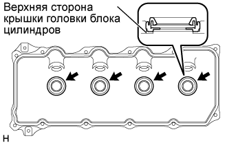
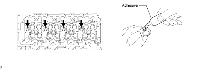
Install 4 new No. 3 cylinder head cover gaskets to the cylinder head cover as shown in the illustration.
Note
-
Do not install the gaskets at an angle.
-
Keep the lip of the gasket free from foreign materials.
-
-
Install a new cylinder head cover gasket to the cylinder head cover.
-
Apply seal packing to the cylinder head as shown in the illustration.
Seal packing Toyota Genuine Seal Packing Black, Three Bond 1207B or equivalent Note
After applying the seal packing, parts must be assembled within 3 minutes, and then tighten them within 15 minutes.
-
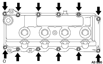
Install the cylinder head cover with 10 bolts and 2 nuts. Uniformly tighten the bolts and nuts in several steps.
- Torque:
- 9.0 N*m { 92 kgf*cm, 80 in.*lbf }
-
-
INSTALL NOZZLE HOLDER SEAL
-
Install 4 new holder seals.
-
-
INSTALL OIL FILLER CAP SUB-ASSEMBLY
-
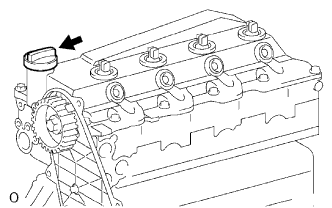
Install the oil filler cap.
-