MULTI-MODE MANUAL TRANSAXLE SYSTEM TERMINALS OF ECU
TCM (Transmission Control ECU)

Terminal No.
(Symbol)
Wiring Color
Terminal Description
Condition
Specified Condition
A108-1 (CAN+) - A108-2 (CAN-)
R - SB
CAN communication
Ignition switch ON
Pulse generation
(See waveform 1)
A108-3 (TMN) - E104-6 (GND)
LG - BR
Neutral position switch
Ignition switch ON, shift lever in N
11 to 14 V
Ignition switch ON, shift lever not in N
Below 1 V
A108-4 (STRL) - E104-6 (GND)
G - BR
Starter relay operation signal (output)
Ignition switch off, brake pedal depressed, shift lever in N → Starter operates
Below 1 V → 11 to 14 V
A108-5 (MREL) - E104-6 (GND)
R - BR
MMT relay (motor power source)
Ignition switch off
Below 1 V
Ignition switch ON
11 to 14 V
A108-6 (STA) - E104-6 (GND)
LG - BR
Starter relay operation signal (input)
Ignition switch off, brake pedal depressed, shift lever in N → Starter operates
Below 1 V → 11 to 14 V
A108-10 (NE) - E104-6 (GND)
L - BR
Engine speed signal from ECM
Engine idling
Pulse generation
(See waveform 2)
A108-16 (NIP+) - A108-15 (NIP-)
P - V
Transmission revolution sensor
Vehicle speed of approximately 30 km/h (19 mph)
Pulse generation
(See waveform 3)
A108-17 (E2S1) - E104-6 (GND)
G - BR
Shift stroke sensor ground (main)
Always
Below 1 Ω
A108-18 (VSS1) - E104-6 (GND)
B - BR
Shift stroke sensor voltage monitor (main)
Ignition switch ON
0.5 V to 4.5 V
A108-19 (VCS1) - E104-6 (GND)
SB - BR
Shift stroke sensor power source (main)
Ignition switch ON
4.7 V to 5.3 V
A108-20 (VCL1) - E104-6 (GND)
W - BR
Select stroke sensor power source (main)
Ignition switch ON
4.7 V to 5.3 V
A108-21 (VSL1) - E104-6 (GND)
B - BR
Select stroke sensor voltage monitor (main)
Ignition switch ON
0.5 V to 4.5 V
A108-22 (E2L1) - E104-6 (GND)
G - BR
Select stroke sensor ground (main)
Always
Below 1 Ω
A108-23 (SPD) - E104-6 (GND)
V - BR
Vehicle speed signal
Vehicle speed of approximately 20 km/h (12 mph)
Pulse generation
(See waveform 4)
A108-24 (E2L2) - E104-6 (GND)
GR - BR
Select stroke sensor ground (sub)
Always
Below 1 Ω
A108-25 (E2R1) - E104-6 (GND)
G - BR
Clutch stroke sensor ground (main)
Always
Below 1 Ω
A108-26 (VSR1) - E104-6 (GND)
B - BR
Clutch stroke sensor voltage monitor (main)
Ignition switch ON
0.5 V to 4.5 V
A108-27 (VCR1) - E104-6 (GND)
W - BR
Clutch stroke sensor power source (main)
Ignition switch ON
4.7 V to 5.3 V
A108-28 (E2S2) - E104-6 (GND)
GR - BR
Shift stroke sensor ground (sub)
Always
Below 1 Ω
A108-29 (VSS2) - E104-6 (GND)
P - BR
Shift stroke sensor voltage monitor (sub)
Ignition switch ON
0.5 V to 4.5 V
A108-30 (VCS2) - E104-6 (GND)
R - BR
Shift stroke sensor power source (sub)
Ignition switch ON
4.7 V to 5.3 V
A108-31 (VCL2) - E104-6 (GND)
R - BR
Select stroke sensor power source (sub)
Ignition switch ON
4.7 V to 5.3 V
A108-32 (VSL2) - E104-6 (GND)
L - BR
Select stroke sensor voltage monitor (sub)
Ignition switch ON
0.5 V to 4.5 V
A108-33 (E2R2) - E104-6 (GND)
SB - BR
Clutch stroke sensor ground (sub)
Always
Below 1 Ω
A108-34 (VSR2) - E104-6 (GND)
G - BR
Clutch stroke sensor voltage monitor (sub)
Ignition switch ON
0.5 V to 4.5 V
A108-35 (VCR2) - E104-6 (GND)
R - BR
Clutch stroke sensor power source (sub)
Ignition switch ON
4.7 V to 5.3 V
A104-1 (PGND) - Body ground
W-B - Body ground
Ground
Always
Below 1 Ω
A104-2 (+BM) - E104-6 (GND)
L - BR
Motor power source
Ignition switch off
Below 1 V
Ignition switch ON
11 to 14 V
A104-3 (MSF-) - E104-6 (GND)
W - BR
Shift motor
Ignition switch ON, shift motor not operating
Below 1 V
Shift motor operating
Pulse generation
(See waveform 5)
A104-4 (MSF+) - E104-6 (GND)
R - BR
Shift motor
Ignition switch ON, shift motor not operating
Below 1 V
Shift motor operating
Pulse generation
(See waveform 5)
A104-5 (MCL-) - E104-6 (GND)
R - BR
Clutch motor
Ignition switch ON, clutch motor not operating
Below 1 V
Clutch motor operating
Pulse generation
(See waveform 6)
A104-6 (MCL+) - E104-6 (GND)
R - BR
Clutch motor
Ignition switch ON, clutch motor not operating
Below 1 V
Clutch motor operating
Pulse generation
(See waveform 6)
A103-1 (MSL+) - E104-6 (GND)
B - BR
Select motor
Ignition switch ON, select motor not operating
Below 1 V
Select motor operating
Pulse generation
(See waveform 7)
A103-2 (MSL-) - E104-6 (GND)
L - BR
Select motor
Ignition switch ON, select motor not operating
Below 1 V
Select motor operating
Pulse generation
(See waveform 7)
E104-1 (+B) - E104-6 (GND)
W - BR
Battery (ECU power source)
Always
11 to 14 V
E104-3 (IG) - E104-6 (GND)
GR - BR
Ignition switch
Ignition switch off
Below 1 V
Ignition switch ON
11 to 14 V
E104-4 (PKB) - E104-6 (GND)
B - BR
Parking brake switch
Ignition switch ON, parking brake switch OFF (parking brake lever released)
11 to 14 V
Ignition switch ON, parking brake switch ON (parking brake lever pulled)
Below 1 V
E104-5 (SLS) - E104-6 (GND)
L - BR
Shift lock solenoid
Ignition switch ON, brake pedal depressed
11 to 14 V
Ignition switch ON, brake pedal released
Below 1 V
E104-6 (GND) - Body ground
BR - Body ground
Ground
Always
Below 1 Ω
E104-8 (SFTD) - E104-6 (GND)
R - BR
Shift paddle switch
Ignition switch ON, "-" shift paddle switch pulled continuously
Below 1 V
Ignition switch ON, "-" shift paddle switch released
11 to 14 V
E104-9 (SFTU) - E104-6 (GND)
W - BR
Shift paddle switch
Ignition switch ON, "+" shift paddle switch pulled continuously
Below 1 V
Ignition switch ON, "+" shift paddle switch released
11 to 14 V
E104-10 (MDSW) - E104-6 (GND)
GR - BR
Transmission shift main switch
Ignition switch ON, shift lever in E
11 to 14 V
Ignition switch ON, shift lever in M
Below 1 V
E104-11 (LS4C) - E104-6 (GND)
P - BR
Shift lever position sensor
Ignition switch ON, shift lever in N
11 to 14 V
Ignition switch ON, shift lever not in N
Below 1 V
E104-12 (LS3C) - E104-6 (GND)
L - BR
Shift lever position sensor
Ignition switch ON, shift lever in E or M
11 to 14 V
Ignition switch ON, shift lever in R or N
Below 1 V
E104-13 (LS2C) - E104-6 (GND)
R - BR
Shift lever position sensor
Ignition switch ON, shift lever in R
11 to 14 V
Ignition switch ON, shift lever not in R
Below 1 V
E104-15 (LSW5) - E104-6 (GND)
LG - BR
Shift lever position sensor
Ignition switch ON, shift lever not in "-"
11 to 14 V
Ignition switch ON, shift lever in "-"
Below 1 V
E104-16 (LSW4) - E104-6 (GND)
G - BR
Shift lever position sensor
Ignition switch ON, shift lever not in N
11 to 14 V
Ignition switch ON, shift lever in N
Below 1 V
E104-17 (LSW3) - E104-6 (GND)
B - BR
Shift lever position sensor
Ignition switch ON, shift lever in R or N
11 to 14 V
Ignition switch ON, shift lever not in R and N
Below 1 V
E104-18 (LSW2) - E104-6 (GND)
W - BR
Shift lever position sensor
Ignition switch ON, shift lever not in R
11 to 14 V
Ignition switch ON, shift lever in R
Below 1 V
E104-19 (LSW1) - E104-6 (GND)
GR - BR
Shift lever position sensor
Ignition switch ON, shift lever not in "+"
11 to 14 V
Ignition switch ON, shift lever in "+"
Below 1 V
E104-23 (ESSW) - E104-6 (GND)
SB - BR
Es mode switch (combination switch assembly)
Ignition switch ON, Es mode switch (combination switch assembly) being pushed
Below 1 V
Ignition switch ON, Es mode switch (combination switch assembly) not being pushed
11 to 14 V
E104-24 (SIL) - E104-6 (GND)
LG - BR
Terminal SIL of DLC3
Ignition switch ON
11 to 14 V
E104-27 (WFSE) - E104-6 (GND)
SB - BR
Terminal WFSE of DLC3
Ignition switch ON
11 to 14 V
E104-29 (INDC) - E104-6 (GND)
GR - BR
Communication line with combination meter
Ignition switch ON
Below 1.44 V
E104-31 (INDA) - E104-6 (GND)
LG - BR
Communication line with combination meter
Ignition switch ON
Pulse generation
(See waveform 8)
E104-34 (STP) - E104-6 (GND)
L - BR
Stop light switch
Brake pedal depressed
11 to 14 V
Brake pedal released
Below 1 V
E104-35 (ST1-) - E104-6 (GND)
G - BR
Stop light switch
Ignition switch ON, brake pedal released
11 to 14 V
Ignition switch ON, brake pedal depressed
Below 1 V
-
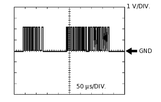
Waveform 1:
CAN Communication Terminal (Reference)
Item
Condition
Terminal
CAN+ - CAN-
Tool setting
1 V/DIV., 50 μs/DIV.
Vehicle condition
Ignition switch ON
-
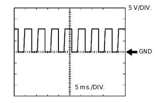
Waveform 2:
Engine Speed Signal from ECM
Item
Condition
Terminal
NE - GND
Tool setting
5 V/DIV., 5 ms./DIV.
Vehicle condition
Engine idling
-
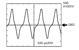
Waveform 3:
Transmission Revolution Sensor Terminal
Item
Condition
Terminal
NIP+ - NIP-
Tool setting
500 mV/DIV., 500 μs/DIV.
Vehicle condition
Vehicle speed of approximately 30 km/h (19 mph)
-
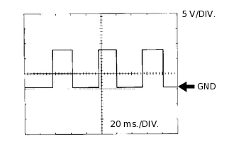
Waveform 4:
Vehicle Speed Signal Terminal
Item
Condition
Terminal
SPD - GND
Tool setting
5 V/DIV., 20 ms./DIV.
Vehicle condition
Vehicle speed of approximately 20 km/h (12 mph)
-
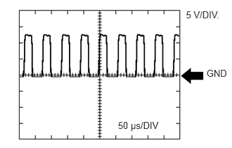
Waveform 5:
Shift Motor Terminal (Reference)
Item
Condition
Terminal
MSF- - GND
MSF+ - GND
Tool setting
5 V/DIV., 50 μs/DIV.
Vehicle condition
Shift motor operating
-
Waveform 6:
Clutch Motor Terminal (Reference)
Item
Condition
Terminal
MCL- - GND
MCL+ - GND
Tool setting
5 V/DIV., 50 μs/DIV.
Vehicle condition
Clutch motor operating
-
Waveform 7:
Select Motor Terminal (Reference)
Item
Condition
Terminal
MSL- - GND
MSL+ - GND
Tool setting
5 V/DIV., 50 μs/DIV.
Vehicle condition
Select motor operating
-
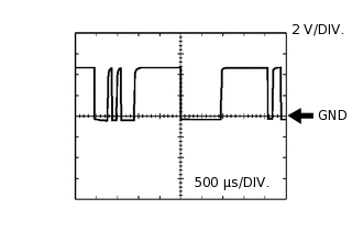
Waveform 8:
Communication with Combination Meter
Item
Condition
Terminal
INDA - GND
Tool setting
2 V/DIV., 500 μs/DIV.
Vehicle condition
Ignition switch ON
-
-
ECM
Terminal No. (Symbol)
Wiring Color
Terminal Description
Condition
Specified Condition
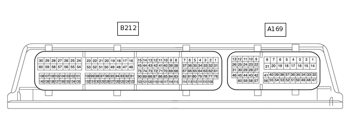
A169-6 (NEO) - A169-4 (E1)
L - W-B
Engine speed
Idling
Pulse generation
(See waveform 1)
A169-30 (CANP) - A169-4 (E1)
B - W-B
CAN communication line
Ignition switch ON
Pulse generation
(See waveform 2)
A169-31 (CANN) - A169-4 (E1)
SB - W-B
CAN communication line
Ignition switch ON
Pulse generation
(See waveform 3)
-
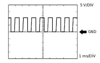
Waveform 1:
Table 1. Engine Speed Signal ECM Terminal Name
NEO and E1
Tester Range
5 V/DIV, 1 ms/DIV
Condition
Idling
Tip:The waveform varies depending on the crankshaft position sensor signal.
-
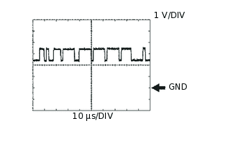
Waveform 2:
Table 2. CAN Communication Signal (Reference) ECM Terminal Name
CANP and E1
Tester Range
1 V/DIV, 10 μs/DIV
Condition
Ignition switch ON
Tip:The wavelength becomes shorter depending on the CAN communication signal.
-
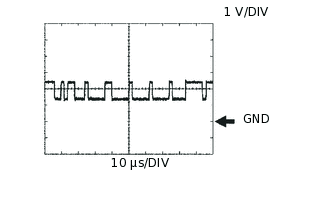
Waveform 3:
Table 3. CAN Communication Signal (Reference) ECM Terminal Name
CANN and E1
Tester Range
1 V/DIV, 10 μs/DIV
Condition
Ignition switch ON
Tip:The wavelength becomes shorter depending on the CAN communication signal.
-