STOP AND START SYSTEM Backup Boost Converter Circuit
| DTC Code | DTC Name |
|---|---|
| Backup Boost Converter Circuit |
DESCRIPTION
A backup boost converter is built into the engine stop and start ECU. The backup boost converter helps maintain the power source voltage when the engine is restarted by stop and start control.
This prevents various functions such as the audio and visual system or navigation system from failing if the power source voltage drops due to the battery voltage dropping when the engine is restarted by stop and start control. If a DTC is output, troubleshoot the DTC first.
A relay function and fuse function are provided in the backup boost converter.
If there is a malfunction in any of the electrical system circuits connected to the backup boost converter, the fuse and relay functions shut off the malfunctioning circuit to protect other circuits (remains shut off until next trip).
When the electrical system circuit is shut off, power to the circuit is cut off, causing any systems connected to the circuit to be disabled.
The fuse function is reset* when the ignition switch is turned off. If the malfunction still exists in the electrical system circuit that has been shut off by the relay function, it will be shut off again by the relay and fuse functions the next time the ignition switch is turned to ON.
*: A semiconductor fuse self-resets according to electric signals.
Backup boost converter supplies power to:
Vehicle stability control system
Power steering system
Meter/gauge system
Audio and visual system or navigation system
Automatic glare-resistant EC mirror
TOYOTA parking assist-sensor system
Tire pressure warning system
WIRING DIAGRAM
Refer to DTC B22C0 (Click here).
CAUTION / NOTICE / HINT
Before replacing the engine stop and start ECU, read the number of starter operations and write it into a new engine stop and start ECU (Click here).
After replacing the engine stop and start ECU or air conditioning amplifier assembly, reset and perform learning of the air conditioning information in the engine stop and start ECU (Click here).
After replacing the engine stop and start ECU or yaw rate sensor, clear and calibrate the deceleration sensor zero point in the engine stop and start ECU (Click here).
Inspect the fuses for circuits related to this system before performing the following procedure.
PROCEDURE
CHECK PROBLEM SYMPTOMS
Determine the trouble area by referring to the table below.
Effect on Vehicle
Trouble Area/Cause
Fail-safe
DTC Output
Stop and start cancel indicator light
Symptom
Proceed to
When the engine is restarted by stop and start control, the following symptoms may occur.
The audio and visual system or navigation system is reset
The combination meter assembly fades out
The steering wheel feels heavy when the engine is restarted*
*: A DTC may be stored in the power steering system
Backup boost converter internal malfunction
Internal power source malfunction
Internal power source overvoltage
Duty error
Communication cycle error
Stop and start control prohibited
P323B
Blinks
Converter output voltage cannot be boosted when the engine is restarted
A
Battery voltage drop
Systems on the converter output side do not operate
BO1 terminal: The audio and visual system or navigation system will not function
IGO1 terminal: All of the following will not operate
Vehicle stability control system
Power steering system
Automatic glare-resistant EC mirror
TOYOTA parking assist-sensor system
Tire pressure warning system
Overcurrent applied to an output terminal (output terminal relay circuit is shutoff)
Stop and start control is prohibited (Connected ECUs or sensors may detect power source malfunction DTCs)
B22C0
Blinks
Systems do not operate as power supply from the converter is cut off
A
Systems do not operate
(Due to converter input side malfunction)
IG1 terminal: All of the following do not operate
Vehicle stability control system
Power steering system
TOYOTA parking assist-sensor system
Automatic glare-resistant EC mirror
Tire pressure warning system
IG2 terminal: The combination meter assembly will not function
ACC terminal: The audio will not function
Converter input circuit malfunction
Open or short to GND in IG1 circuit
Open or short to GND in IG2 circuit
Open or short to GND in ACC circuit
Stop and start control prohibited
-
Does not blink (Blinks when communication error DTCs are stored)
Systems do not operate as power supply from the converter is cut off
B
Systems on the converter output side do not operate
(varies depending on the malfunctioning relay circuit the converter detected)
ACO terminal: The audio and visual system or navigation system will not function
IGO2 terminal: The combination meter assembly will not function
Malfunction in circuits the converter supplies power to
(between the converter and ECUs or sensors)
Open or short in the combination meter assembly circuit
Related systems do not operate as the relay circuit in the converter is turned off
-
Does not blink (Blinks when communication error DTCs are stored)
Systems do not operate as power supply from the converter is cut off
B
All of the following will operate
Audio and visual system or navigation system
Vehicle stability control system
Power steering system
TOYOTA parking assist-sensor system
Meter/gauge system
Automatic glare-resistant EC mirror
Tire pressure warning system
Open in BBC fuse circuit
Short in converter circuit
Backup boost converter malfunction
Stop and start control prohibited
P0617
Does not blink (Due to disabled meter/gauge system)
All systems that the converter supplies power to do not operate (see circuit diagram)
A
P323B
The audio and visual system or navigation system does not function
(until the ignition switch is turned off)
Excessive audio volume
Data List item "State of BBC" displays "BBC Overcurrent" while the circuit is protected
The relay circuit in the converter is turned off to cut off power supply to the audio and visual system or navigation system (Returns to normal when the ignition switch is turned off)
-
Does not blink
If overcurrent is detected in the audio and visual system or navigation system, system operation is disabled while the ignition switch is ON
(Returns to normal when the ignition switch is turned off)
C
The audio and visual system or navigation system cannot be turned off (short between ACO and +B)
The combination meter assembly cannot be turned off (short between IGO2 and +B)
Communication error DTCs may be stored due to short between IGO1 and +B
Tip:Varies depending on the number of times an open occurs in the +B circuit
Converter circuit malfunction
Short between ACO and +B
Short between IGO1 and +B
Short between IGO2 and +B
-
-
Does not blink
The converter cannot shut off power source when the ignition switch is turned off
B
Ignition switch does not turn to ACC (short between ACC and +B)
Ignition switch does not turn off (short between IG1 or IG2 and +B)
Engine stop and start ECU power source circuit malfunction
Short between ACC and +B
Short between IG1 and +B
Short between IG2 and +B
-
-
Does not blink
Ignition switch does not turn to ACC
Ignition switch does not turn off
B
CHECK AUDIO AND VISUAL SYSTEM OR NAVIGATION SYSTEMClick here
CHECK ENGINE STOP AND START ECU (POWER SOURCE CIRCUIT)
-
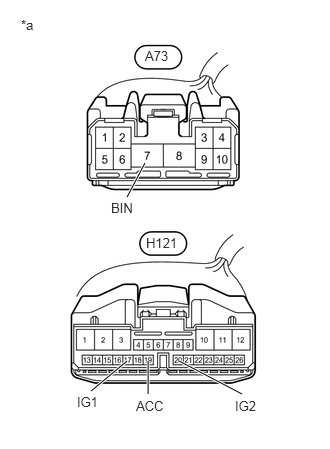
Disconnect the A73 and H121 engine stop and start ECU connectors.
Measure the voltage according to the value(s) in the table below.
Standard Voltage
Tester Connection
Condition
Specified Condition
A73-7 (BIN) - Body ground
Always
9.5 to 14 V
Turn the ignition switch to ACC.
Measure the voltage according to the value(s) in the table below.
Standard Voltage
Tester Connection
Switch Condition
Specified Condition
H121-19 (ACC) - Body ground
Ignition switch ACC
9.5 to 14 V
Turn the ignition switch to ON.
Measure the voltage according to the value(s) in the table below.
Standard Voltage
Tester Connection
Switch Condition
Specified Condition
H121-17 (IG1) - Body ground
Ignition switch ON
9.5 to 14 V
H121-20 (IG2) - Body ground
Ignition switch ON
9.5 to 14 V
Turn the ignition switch off.
Measure the voltage according to the value(s) in the table below.
Standard Voltage
Tester Connection
Switch Condition
Specified Condition
H121-17 (IG1) - Body ground
Ignition switch off
0 to 1 V
H121-19 (ACC) - Body ground
Ignition switch off
0 to 1 V
H121-20 (IG2) - Body ground
Ignition switch off
0 to 1 V
Table 1. Text in Illustration *a
Front view of wire harness connector
(to Engine Stop and Start ECU)
REPAIR OR REPLACE HARNESS OR CONNECTOR
-
CHECK HARNESS AND CONNECTOR (ENGINE STOP AND START ECU - EACH ECU OR SENSOR)
Disconnect the connector from the corresponding system ECU/sensor.
Measure the resistance according to the value(s) in the table below.
Standard Resistance
Radio Receiver Assembly (for Radio Receiver Type)
Tester Connection
Condition
Specified Condition
H121-2 (BO1) - H1-4 (+B1)
Always
Below 1 Ω
H121-3 (ACO) - H1-3 (ACC1)
Always
Below 1 Ω
H121-2 (BO1) - Body ground
Always
10 kΩ or higher
H121-3 (ACO) - Body ground
Always
10 kΩ or higher
H1-4 (+B1) - Body ground
Always
10 kΩ or higher
H1-3 (ACC1) - Body ground
Always
10 kΩ or higher
Radio and Display Receiver Assembly (for Radio and Display Receiver Type)
Tester Connection
Condition
Specified Condition
H121-2 (BO1) - H107-4 (+B1)
Always
Below 1 Ω
H121-3 (ACO) - H107-3 (ACC1)
Always
Below 1 Ω
H121-2 (BO1) - Body ground
Always
10 kΩ or higher
H121-3 (ACO) - Body ground
Always
10 kΩ or higher
H107-4 (+B1) - Body ground
Always
10 kΩ or higher
H107-3 (ACC1) - Body ground
Always
10 kΩ or higher
Skid Control ECU (Brake Actuator Assembly)
Tester Connection
Condition
Specified Condition
H121-12 (IGO1) - A79-4 (IG1)
Always
Below 1 Ω
H121-12 (IGO1) - Body ground
Always
10 kΩ or higher
A79-4 (IG1) - Body ground
Always
10 kΩ or higher
Steering Angle Sensor (Spiral with Sensor Cable Sub-assembly)
Tester Connection
Condition
Specified Condition
H121-12 (IGO1) - H128-5 (IG)
Always
Below 1 Ω
H121-12 (IGO1) - Body ground
Always
10 kΩ or higher
H128-5 (IG) - Body ground
Always
10 kΩ or higher
Yaw Rate Sensor
Tester Connection
Condition
Specified Condition
H121-12 (IGO1) - H68-1 (IGA)
Always
Below 1 Ω
H121-12 (IGO1) - Body ground
Always
10 kΩ or higher
H68-1 (IGA) - Body ground
Always
10 kΩ or higher
Power Steering ECU Assembly
Tester Connection
Condition
Specified Condition
H121-12 (IGO1) - H49-5 (IG)
Always
Below 1 Ω
H121-12 (IGO1) - Body ground
Always
10 kΩ or higher
H49-5 (IG) - Body ground
Always
10 kΩ or higher
Combination Meter Assembly
Tester Connection
Condition
Specified Condition
H121-11 (IGO2) - H62-39 (IG+)
Always
Below 1 Ω
H121-11 (IGO2) - Body ground
Always
10 kΩ or higher
H62-39 (IG+) - Body ground
Always
10 kΩ or higher
Instrument Panel Junction Block Assembly (Main Body ECU (Multiplex Network Body ECU))
Tester Connection
Condition
Specified Condition
H121-12 (IGO1) - DH-13 (IG)
Always
Below 1 Ω
H121-12 (IGO1) - Body ground
Always
10 kΩ or higher
DH-13 (IG) - Body ground
Always
10 kΩ or higher
Inner Rear View Mirror Assembly (w/ Automatic Glare-resistant EC mirror)
Tester Connection
Condition
Specified Condition
H121-12 (IGO1) - Q9-4 (IG)
Always
Below 1 Ω
H121-12 (IGO1) - Body ground
Always
10 kΩ or higher
Q9-4 (IG) - Body ground
Always
10 kΩ or higher
Tire Pressure Warning ECU and Receiver (w/ Tire Pressure Warning System)
Tester Connection
Condition
Specified Condition
H121-12 (IGO1) - N32-1 (IG)
Always
Below 1 Ω
H121-12 (IGO1) - Body ground
Always
10 kΩ or higher
N32-1 (IG) - Body ground
Always
10 kΩ or higher
Back Sonar or Clearance Sonar Switch Assembly (w/ TOYOTA Parking Assist-sensor System)
Tester Connection
Condition
Specified Condition
H121-12 (IGO1) - H97-6 (IG)
Always
Below 1 Ω
H121-12 (IGO1) - Body ground
Always
10 kΩ or higher
H97-6 (IG) - Body ground
Always
10 kΩ or higher
REPAIR OR REPLACE HARNESS OR CONNECTOR
CHECK ENGINE STOP AND START ECU (EACH ECU OR SENSOR POWER SOURCE CIRCUIT)
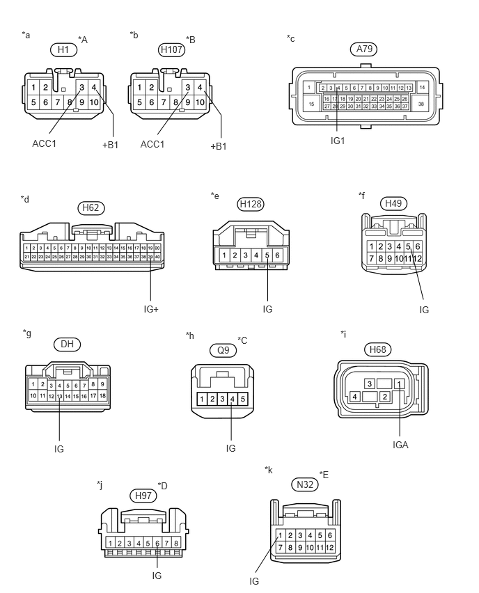
Table 2. Text in Illustration *A
for Radio Receiver Type
*B
for Radio and Display Receiver Type
*C
w/ Automatic Glare-resistant EC mirror
*D
w/ TOYOTA Parking Assist-sensor System
*E
w/ Tire Pressure Warning System
-
-
*a
Front view of wire harness connector
(to Radio Receiver Assembly)
*b
Front view of wire harness connector
(to Radio and Display Receiver Assembly)
*c
Front view of wire harness connector
(to Skid Control ECU (Brake Actuator Assembly))
*d
Front view of wire harness connector
(to Combination Meter Assembly)
*e
Front view of wire harness connector
(to Steering Angle Sensor (Spiral with Sensor Cable Sub-assembly))
*f
Front view of wire harness connector
(to Power Steering ECU Assembly)
*g
Front view of wire harness connector
(to Instrument Panel Junction Block Assembly (Main Body ECU (Multiplex Network Body ECU)))
*h
Front view of wire harness connector
(to Inner Rear View Mirror Assembly)
*i
Front view of wire harness connector
(to Yaw Rate Sensor)
*j
Front view of wire harness connector
(to Back Sonar or Clearance Sonar Switch Assembly)
*k
Front view of wire harness connector
(to Tire Pressure Warning ECU and Receiver)
-
-
Disconnect the connector from the corresponding system ECU/sensor.
Measure the voltage according to the value(s) in the table below.
Tip:Measure the voltage at the corresponding terminals.
Standard Voltage
Radio Receiver Assembly (for Radio Receiver Type)
Tester Connection
Condition
Specified Condition
H1-4 (+B1) - Body ground
Always
9.5 to 14 V
Radio and Display Receiver Assembly (for Radio and Display Receiver Type)
Tester Connection
Condition
Specified Condition
H107-4 (+B1) - Body ground
Always
9.5 to 14 V
Turn the ignition switch to ACC.
Measure the voltage according to the value(s) in the table below.
Tip:Measure the voltage at the corresponding terminals.
Standard Voltage
Radio Receiver Assembly (for Radio Receiver Type)
Tester Connection
Switch Condition
Specified Condition
H1-3 (ACC1) - Body ground
Ignition switch ACC
9.5 to 14 V
Radio and Display Receiver Assembly (for Radio and Display Receiver Type)
Tester Connection
Switch Condition
Specified Condition
H107-3 (ACC1) - Body ground
Ignition switch ACC
9.5 to 14 V
Turn the ignition switch to ON.
Measure the voltage according to the value(s) in the table below.
Tip:Measure the voltage at the corresponding terminals.
Standard Voltage
Tester Connection
Switch Condition
Specified Condition
A79-4 (IG1) - Body ground
Ignition switch ON
9.5 to 14 V
H62-39 (IG+) - Body ground
Ignition switch ON
9.5 to 14 V
H128-5 (IG) - Body ground
Ignition switch ON
9.5 to 14 V
H49-5 (IG) - Body ground
Ignition switch ON
9.5 to 14 V
DH-13 (IG) - Body ground
Ignition switch ON
9.5 to 14 V
H68-1 (IGA) - Body ground
Ignition switch ON
9.5 to 14 V
Q9-4 (IG) - Body ground*1
Ignition switch ON
9.5 to 14 V
H97-6 (IG) - Body ground*2
Ignition switch ON
9.5 to 14 V
N32-1 (IG) - Body ground*3
Ignition switch ON
9.5 to 14 V
*1: w/ Automatic Glare-resistant EC Mirror
*2: w/ TOYOTA Parking Assist-sensor System
*3: w/ Tire Pressure Warning System
CHECK POWER SOURCE CIRCUIT (POWER SOURCE CIRCUIT OF RELATED SYSTEM)
CHECK AUDIO AND VISUAL SYSTEM OR NAVIGATION SYSTEM
Turn the ignition switch off and wait for 1 minute.
Turn the ignition switch to ON.
Lower the audio volume.
for Radio Receiver Type/Radio and Display Receiver Type (Audio and Visual System):
Check if the audio and visual system operates normally.
OK
Audio and visual system operates normally.
for Radio and Display Receiver Type (Navigation system):
Check if the navigation system operates normally.
OK
Navigation system operates normally.
END
CHECK HARNESS AND CONNECTOR (ENGINE STOP AND START ECU - RADIO AND DISPLAY RECEIVER)
Disconnect the H121 engine stop and start ECU connector.
for Radio Receiver Type:
Disconnect the H1 radio receiver assembly connector.
for Radio and Display Receiver Type:
Disconnect the H107 radio and display receiver assembly connector.
Measure the resistance according to the value(s) in the table below.
Standard Resistance
for Radio Receiver Type
Tester Connection
Condition
Specified Condition
H121-2 (BO1) - Body ground
Always
10 kΩ or higher
H1-4 (+B1) - Body ground
Always
10 kΩ or higher
H121-3 (ACO) - Body ground
Always
10 kΩ or higher
H1-3 (ACC1) - Body ground
Always
10 kΩ or higher
for Radio and Display Receiver Type
Tester Connection
Condition
Specified Condition
H121-2 (BO1) - Body ground
Always
10 kΩ or higher
H107-4 (+B1) - Body ground
Always
10 kΩ or higher
H121-3 (ACO) - Body ground
Always
10 kΩ or higher
H107-3 (ACC1) - Body ground
Always
10 kΩ or higher
Table 3. Result Result
Proceed to
OK (for Radio Receiver Type: Audio Visual System)
A
OK (for Radio and Display Receiver Type: Audio Visual System)
B
OK (for Radio and Display Receiver Type: Navigation System)
C
NG
D
REPAIR OR REPLACE HARNESS OR CONNECTOR