PARKING BRAKE LEVER INSTALLATION
-
INSTALL PARKING BRAKE CONTROL HANDLE ASSEMBLY (LHD)
-
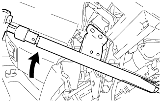
Pass the parking brake cable assembly No.1 out of the cabin.
-
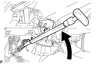
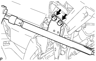
Install the parking brake cable assembly No.1 to the body with the 2 bolts.
- Torque:
- 8.5 N*m { 87 kgf*cm, 75 in.*lbf }
-
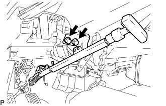
Install the parking brake control handle to the body with the 2 nuts.
- Torque:
- 20 N*m { 204 kgf*cm, 15 ft.*lbf }
Tech Tips
The parking brake control handle should be lowered when installing.
-
Return the parking brake control handle to its initial position.
-
Install the parking brake control handle with the 2 bolts.
- Torque:
- 20 N*m { 204 kgf*cm, 15 ft.*lbf }
-
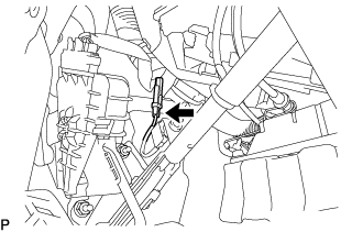
Connect the parking brake switch assembly.
-
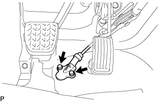
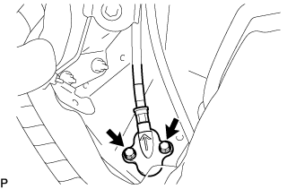
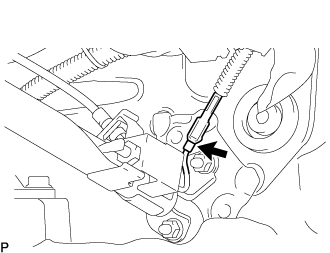
Apply MP grease to the connecting part of the parking brake cable assembly No.1 and the parking brake intermediate lever.
-
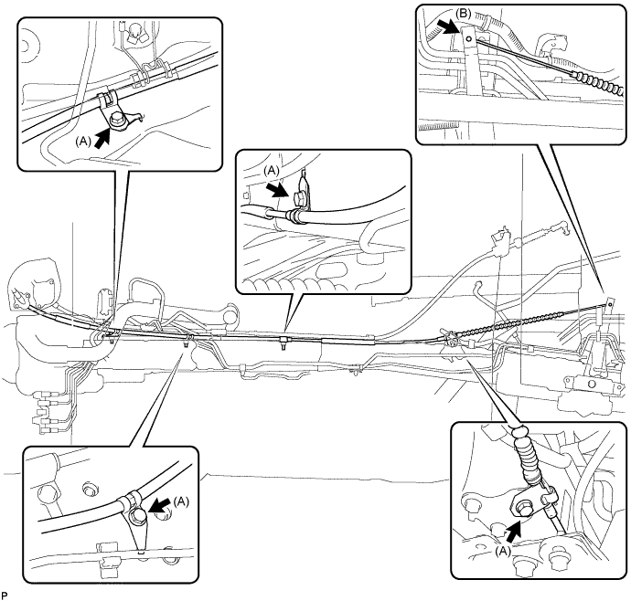
Install the parking brake cable assembly No.1 to the parking brake intermediate lever. (Procedure B)
-
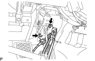
Install the clamps to the parking brake cable assembly No.1.
-
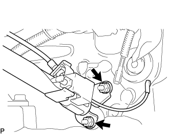
Install the parking brake cable assembly No.1 to the body with the 4 bolts. (Procedure A)
- Torque:
- 14.5 N*m { 148 kgf*cm, 11 ft.*lbf }
-
-
INSTALL PARKING BRAKE CONTROL HANDLE SUB-ASSEMBLY (RHD)
-
Pass the parking brake cable assembly No.1 from the driver side to the passenger side, then out of the cabin.
-
Install the parking brake cable assembly No.1 to the body with the 2 bolts.
- Torque:
- 8.5 N*m { 87 kgf*cm, 75 in.*lbf }
-
Install the parking brake control handle to the body with the 2 nuts.
- Torque:
- 20 N*m { 204 kgf*cm, 15 ft.*lbf }
Tech Tips
The parking brake control handle should be lowered when installing.
-
Return the parking brake control handle to its initial position.
-
Install the parking brake control handle with the 2 bolts.
- Torque:
- 20 N*m { 204 kgf*cm, 15 ft.*lbf }
-
Connect the parking brake switch assembly.
-
Apply MP grease to the connecting part of the parking brake cable assembly No.1 and the parking brake intermediate lever.
-
Install the parking brake cable assembly No.1 to the parking brake intermediate lever. (Procedure B)
-
Install the clamps to the parking brake cable assembly No.1.
-
Install the parking brake cable assembly No.1 to the body with the 4 bolts. (Procedure A)
- Torque:
- 14.5 N*m { 148 kgf*cm, 11 ft.*lbf }
-
-
REMOVE INSTRUMENT PANEL TO FLOOR BRACE SUB-ASSEMBLY (LHD)
-
INSTALL PARKING BRAKE HOLE COVER
-
Attach the 6 claws to install the parking brake hole cover.
-
-
INSTALL INSTRUMENT PANEL UNDER COVER ASSEMBLY NO.1
-
Attach the 3 claws to instrument panel under cover sub-assembly No. 1.
-
Install the the 2 clips.
-
-
INSTALL INSTRUMENT PANEL FINISH PANEL LOWER
-
Connect the fuel lid lock control cable and bonnet (hood) control cable assembly to the instrument panel finish lower.
-
Attach the 4 clips to install the instrument panel finish panel lower.
-
Install the 2 clips.
-
-
INSTALL ENGINE UNDER COVER NO.2
-
INSTALL ENGINE UNDER COVER NO.1
-
INSPECT PARKING BRAKE CONTROL HANDLE TRAVEL
-
Pull firmly on the parking brake control handle.
-
Release the parking brake lock, and return the parking brake control handle to its off position.
-
Slowly pull the parking brake control handle all the way up, and count the number of clicks.
Parking brake control handle travel 10 to 16 clicks at 200 N (20 kgf, 44 lbf) (except Super Long Wheelbase) 12 to 18 clicks at 200 N (20 kgf, 44 lbf) (for Super Long Wheelbase) Tech Tips
-
If the number of clicks falls outside of the specified range, release the parking brake lock and adjust it.
-
If there are fewer clicks than the specified value, loosen the parking brake wire adjustment nut an the lock nut. With the parking brake cable loosened, adjust the clearance between the brake drum and lining.
-
-
-
REMOVE REAR WHEEL
-
ADJUST REAR BRAKE SHOE CLEARANCE
-
Using a screwdriver from a service hole, turn the adjuster to expand the shoes so that the brake shoes touch the brake drum.
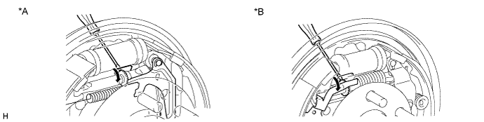
Text in Illustration *A for 295 mm Drum *B for 254 mm Drum -
Using another screwdriver, push up the automatic adjust lever and turn the adjuster to contract the shoes so that the brake shoe does not touch the brake drum. Then turn the adjuster another 180 degrees to further contract the shoes.
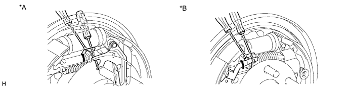
Text in Illustration *A for 295 mm Drum *B for 254 mm Drum -
Install the hole plug.
-
-
INSTALL REAR WHEEL
- Torque:
- 100 N*m { 1,020 kgf*cm, 74 ft.*lbf }
-
ADJUST PARKING BRAKE CONTROL HANDLE TRAVEL
-
Lift the vehicle
-
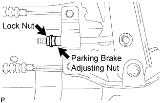
Depress the parking brake handle. Hold the parking brake adjusting nut using a wrench, and loosen the lock nut.
-
Turn the parking brake adjusting nut until the parking brake handle travel meets the above specification.
Parking brake control handle travel 10 to 16 clicks at 200 N (20 kgf, 44 lbf) (except Super Long Wheelbase) 12 to 18 clicks at 200 N (20 kgf, 44 lbf) (for Super Long Wheelbase) -
Count the number of clicks after depressing and releasing the parking brake control handle 3 or 4 times.
-
Check whether the parking brake drags or not.
-
When operating the parking brake control handle, check that the parking brake indicator light comes on.
Standard Brake warning light always comes on at the first click. -
Hold the parking brake adjusting nut using a wrench, and tighten the lock nut.
- Torque:
- 14.5 N*m { 148 kgf*cm, 11 ft.*lbf }
-
Lower the vehicle.
-