STEERING GEAR REMOVAL
-
PRECAUTION
-
DISCONNECT CABLE FROM NEGATIVE BATTERY TERMINAL
CAUTION:
Wait at least 90 seconds after disconnecting the cable from the negative (-) battery terminal to prevent airbag and seat belt pretensioner activation.
-
PLACE FRONT WHEEL FACING STRAIGHT AHEAD
-
REMOVE STEERING PAD ASSEMBLY
-
REMOVE STEERING WHEEL ASSEMBLY
-
Remove the steering wheel assembly set nut.
-
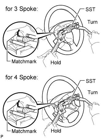
Put matchmarks on the steering wheel assembly and steering main shaft.
-
Using SST, remove the steering wheel assembly.
- SST
- 09950-50013 ( 09951-05010, 09952-05010, 09953-05020, 09954-05021 )
Note
Apply a small amount of grease to the threads and tip of SST (09953-05020) before use.
-
-
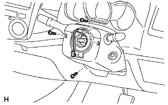
REMOVE STEERING COLUMN COVER LOWER
-
Remove the 3 screws and cover lower.
-
-
REMOVE STEERING COLUMN COVER UPPER
-
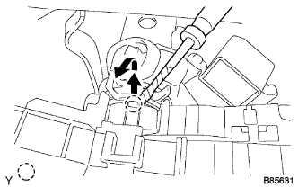
REMOVE WINDSHIELD WIPER SWITCH ASSEMBLY
-
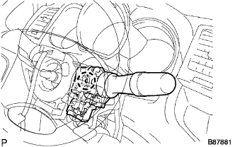
Disconnect the connectors.
-
Detach the claw and remove the windshield wiper switch.
Note
Do not push the claw with excessive force as damage may occur.
-
-
REMOVE HEADLIGHT DIMMER SWITCH ASSEMBLY
-
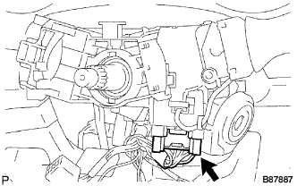
Disconnect the connector.
-
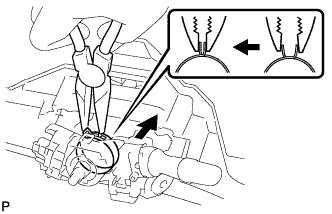
Using needle-nose pliers, remove the band clamp as shown in the illustration.
-
Using a screwdriver, detach the claws and remove the switch.
Tech Tips
Tape the screwdriver tip before use.
-
-
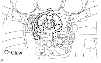
REMOVE SPIRAL CABLE SUB-ASSEMBLY
-
Disconnect the connectors from the spiral cable.
Note
When handling the airbag connector, do not damage the airbag wire harness.
-
Detach the 3 claws and remove the spiral cable.
-
-
REMOVE FRONT WHEEL
-
REMOVE NO. 2 ENGINE UNDER COVER (for 4WD)
-
Remove the 4 bolts and under cover.
-
-
REMOVE NO. 1 ENGINE UNDER COVER (for 4WD)
-
Remove the 4 bolts and under cover.
-
-
REMOVE FRONT SIDE MEMBER TO FRONT SUSPENSION CROSSMEMBER BRACE
-
Remove the 8 bolts and crossmember brace.
-
-
REMOVE FRONT STABILIZER BAR
-
DISCONNECT TIE ROD END SUB-ASSEMBLY LH
-
Remove the cotter pin and nut.
-
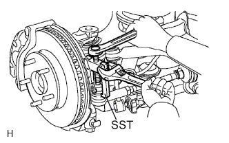
Using SST, disconnect the tie rod end from the steering knuckle arm.
- SST
- 09628-62011
Tech Tips
-
The illustration is for 2WD vehicles.
-
When servicing a 4WD vehicle, use the illustration for 2WD vehicles as a reference.
-
-
DISCONNECT TIE ROD END SUB-ASSEMBLY RH
Tech Tips
Use the same procedures described for the LH side.
-
DISCONNECT STEERING SLIDING YOKE
-
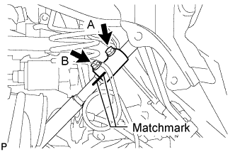
Loosen the bolt labeled A.
-
Make matchmarks on the steering yoke and steering intermediate shaft.
-
Remove the bolt labeled B.
-
Disconnect the steering sliding yoke from the No. 2 steering intermediate shaft.
-
-
REMOVE NO. 2 STEERING INTERMEDIATE SHAFT SUB-ASSEMBLY
-
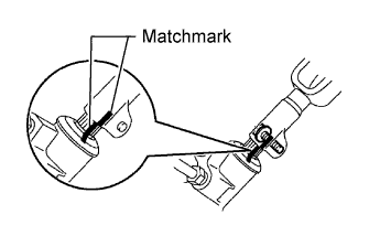
Make matchmarks on the intermediate shaft and steering link.
-
Remove the bolt and intermediate shaft from the steering link.
Note
If the intermediate shaft is struck, replace it with a new one.
-
-
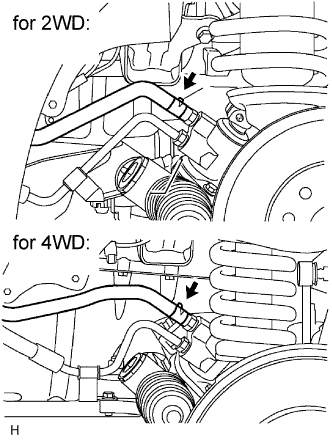
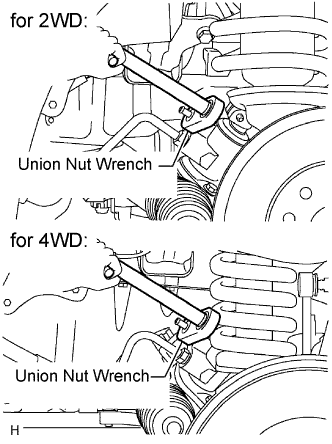
DISCONNECT PRESSURE FEED TUBE ASSEMBLY
-
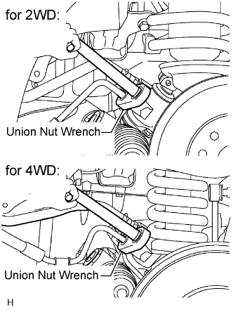
Using a union nut wrench, loosen the flare nut and disconnect the pressure feed tube.
-
Remove the bolt and disconnect the pressure feed tube from the steering link.
-
-
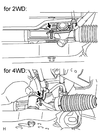
DISCONNECT STEERING GEAR OUTLET RETURN TUBE
-
Remove the clip and disconnect the return hose.
-
Using a union nut wrench, disconnect the outlet return tube.
-
-
REMOVE POWER STEERING LINK ASSEMBLY
-
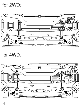
Fix the 2 nuts in place and remove the 2 bolts. Then remove the link from the frame.
Note
Never turn the nut. Be sure to turn the bolt.
Tech Tips
for 4WD:
Removal of the link may be easier if the following is performed: 1) remove the differential mount, and 2) slide the differential toward the rear of the vehicle.
-