FRONT LOWER SUSPENSION ARM(for 2WD) REMOVAL

CAUTION / NOTICE / HINT
The necessary procedures (adjustment, calibration, initialization, or registration) that must be performed after parts are removed, installed, or replaced during the front lower suspension arm removal/installation are shown below.
| Necessary Procedure After Parts Removed/Installed/Replaced | ||||||||||||||||||||||
|---|---|---|---|---|---|---|---|---|---|---|---|---|---|---|---|---|---|---|---|---|---|---|
|
Tech Tips
-
Use the same procedure for the RH and LH side.
-
The following procedure is for the LH side.
PROCEDURE
-
AIR SUSPENSION CONTROL PROHIBITED (w/ Air Suspension)
-
REMOVE FRONT WHEEL
-
REMOVE FRONT LOWER SUSPENSION ARM ASSEMBLY LH
-
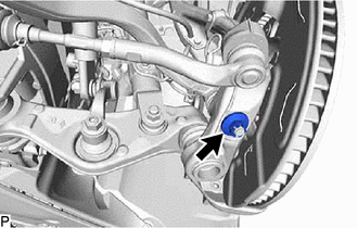
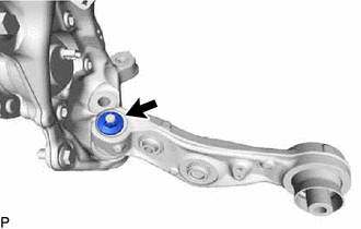
Remove the clip and nut.
-
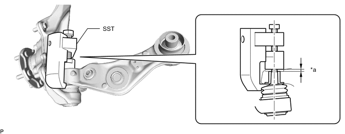
Install 2 SST (spacer A) onto the front lower suspension arm assembly LH so that there is a space of approximately 1 mm (0.0394 in.) between the arm and spacers.
- SST
- 09960-20010 ( 09961-02050 )
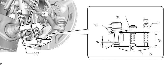
*a SST (Spacer A) *b 1 mm (0.0394 in.) *c Spacer *d Center Nut *e Body *f Claw *g Parallel *h String Note
-
Make sure to install the spacers (SST spacer A) as the steering knuckle spacer may shift.
-
As SST may become damaged, make sure the space between the arm and spacers is not 1 mm (0.0394 in.) or less.
-
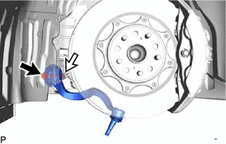
Using SST, disconnect the front lower suspension arm assembly LH from the steering knuckle assembly LH.
- SST
- 09960-20010 ( 09961-02010 )
Note
-
Apply molybdenum grease to the bolt threads and end of the SST bolt.
-
Do not damage the dust cover.
-
As the dust cover may be damaged, adjust SST with the center nut so that the body and claw are parallel.
-
Make sure to tie the string of SST to the vehicle to prevent SST from dropping.
-

Bolt 
Nut Remove the bolt, nut and front lower suspension arm assembly LH.
-
-
DISCONNECT DISC BRAKE CYLINDER ASSEMBLY LH
-
REMOVE FRONT DISC LH
-
for 6-Pot Caliper:
-
except 6-Pot Caliper:
-
-
REMOVE TRANSMISSION UNDER COVER
-
REMOVE NO. 2 ENGINE UNDER COVER ASSEMBLY
-
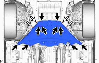
Bolt Screw Remove the 10 bolts, 4 screws, clip and No. 2 engine under cover assembly.
-
-
REMOVE ENGINE SIDE COVER LH
-
Disconnect the clamp and 4 clips and remove the engine side cover LH.
-
-
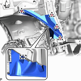
REMOVE REAR LOWER ARM MOUNTING REINFORCEMENT SUB-ASSEMBLY LH
-
Remove the 4 bolts and rear lower arm mounting reinforcement sub-assembly LH.
-
-
DISCONNECT FRONT HEIGHT CONTROL SENSOR SUB-ASSEMBLY LH (w/ Air Suspension)
-
DISCONNECT FRONT STABILIZER LINK ASSEMBLY LH
-
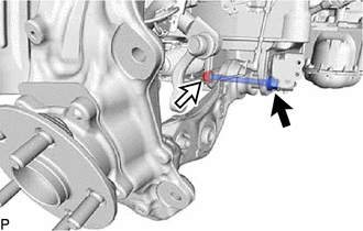
DISCONNECT FRONT SHOCK ABSORBER ASSEMBLY LH (w/o Air Suspension)
-
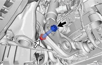
Bolt Nut Remove the bolt and nut, and separate the front shock absorber assembly LH from the lower No. 2 suspension arm assembly LH.
Note
Because the nut has its own stopper, do not turn the nut. Loosen the bolt with the nut secured.
-
-
DISCONNECT FRONT PNEUMATIC CYLINDER WITH SHOCK ABSORBER ASSEMBLY LH (w/ Air Suspension)
Tech Tips
Perform the same procedure as for the front shock absorber assembly LH.
-
DISCONNECT TIE ROD ASSEMBLY LH
-
DISCONNECT STEERING KNUCKLE ASSEMBLY LH
-
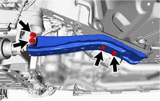
REMOVE LOWER NO. 2 SUSPENSION ARM ASSEMBLY LH
-
Bolt Nut Remove the bolt, nut and lower No. 2 suspension arm assembly LH.
-
Remove the clip and nut.
-
Install SST (attachment) onto the lower No. 2 suspension arm assembly LH so that there is a space of approximately 2 mm (0.0787 in.) between the arm and attachment.
- SST
- 09628-50010 ( 09628-05010 )
*a 2 mm (0.0787 in.) - - Note
-
Make sure to install the attachment (SST attachment) as the lower No. 2 suspension arm assembly LH spacer may shift.
-
As SST may become damaged, make sure the space between the arm and spacers is not 2 mm (0.0787 in.) or less.
-
Using SST, disconnect the lower No. 2 suspension arm assembly LH from the steering knuckle assembly LH.
- SST
- 09628-50010 ( 09628-05010 )
Note
-
Apply molybdenum grease to the bolt threads and end of the SST bolt.
-
Do not damage the dust cover.
-
As the dust cover may be damaged, adjust SST with the center nut so that the body and crow are parallel.
-
Do not apply a torque of 160 N*m (1631 kgf*cm, 118 ft.*lbf) or more to SST as it may be damaged.
-