RADIATOR INSTALLATION
PROCEDURE
-
INSTALL FAN SHROUD
-
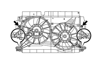
Insert the fan shroud hooks into the radiator holes and install the fan shroud with the 2 bolts.
- Torque:
- 7.0 N*m { 71 kgf*cm, 62 in.*lbf }
-
-
INSTALL INTERCOOLER ASSEMBLY
-
INSTALL LOWER RADIATOR SUPPORT SUB-ASSEMBLY
-
INSTALL NO. 2 RADIATOR HOSE
-
Install the No. 2 radiator hose to the radiator assembly, and slide the hose clamp to secure the hose.
-
Connect the No. 2 radiator hose to the water by-pass hose sub-assembly and close the water hose hose clamp.
-
-
INSTALL RADIATOR ASSEMBLY
-
Install the 2 cushions.
-
Install the radiator assembly together with the intercooler assembly.
Note
Do not allow the radiator assembly to interfere with other parts.
-
Attach the clamp and connect the 2 connectors.
-
-
INSTALL CONDENSER ASSEMBLY WITH RECEIVER (w/ Air Conditioning System)
-
INSTALL RADIATOR GRILLE BRACKET
-
Install the radiator grille bracket with the bolt.
- Torque:
- 13 N*m { 127 kgf*cm, 9 ft.*lbf }
-
Connect the 2 connectors to the 2 horns.
-
-
INSTALL HOOD LOCK SUPPORT SUB-ASSEMBLY
-
Install the hood lock support sub-assembly with the 5 bolts.
- Torque:
- 13 N*m { 127 kgf*cm, 9 ft.*lbf }
-
Attach the clamp to connect the hood lock control cable assembly to the hood lock support sub-assembly.
-
-
INSTALL HOOD LOCK ASSEMBLY
-
INSTALL UPPER RADIATOR SUPPORT SUB-ASSEMBLY
-
Install the 2 upper radiator support sub-assemblies with the 4 bolts.
- Torque:
- 7.0 N*m { 71 kgf*cm, 62 in.*lbf }
-
Install the 2 cushions.
-
-
INSTALL UPPER RADIATOR SUPPORT
-
Install the 2 upper radiator supports with the 2 bolts.
- Torque:
- 19 N*m { 194 kgf*cm, 14 ft.*lbf }
-
-
CONNECT SUCTION PIPE SUB-ASSEMBLY (w/ Air Conditioning System)
-
CONNECT DISCHARGE HOSE SUB-ASSEMBLY (w/ Air Conditioning System)
-
CONNECT NO. 2 RADIATOR HOSE
Note
-
Check that the retainer is closed when the connector is inserted.
-
If replacing the hose, apply fresh engine coolant to the O-ring.
-
Push on the connector until it makes a click sound which indicates that the connection is complete. After connecting the connector, check that the connector cannot be disconnected by pulling the connector.
-
Do not use a quick connector that has been dropped.
-
Push in the retainer and connect the No. 2 radiator hose to the water inlet.
-
-
CONNECT NO. 3 AIR HOSE
-
Connect the No. 3 air hose to the intercooler assembly, and tighten the hose clamp to secure the hose.
- Torque:
- 6.5 N*m { 66 kgf*cm, 58 in.*lbf }
-
-
CONNECT NO. 2 AIR HOSE
Note
If replacing the No. 2 air hose, check for deposits in the intercooler assembly and No. 2 air hose. If necessary, wipe up deposits.
-
Connect the No. 2 air hose to the intercooler assembly, and tighten the hose clamp to secure the hose.
- Torque:
- 6.5 N*m { 66 kgf*cm, 58 in.*lbf }
-
-
CONNECT NO. 1 RADIATOR HOSE
-
Connect the No. 1 radiator hose to the radiator assembly, and slide the hose clamp to secure the hose.
-
-
CONNECT NO. 3 WATER BY-PASS HOSE
-
Connect the No. 3 water by-pass hose to the radiator assembly, and slide the hose clamp to secure the hose.
-
Attach the clamp to connect the No. 3 water by-pass hose to the fan shroud.
-
-
CONNECT NO. 2 WATER BY-PASS HOSE
-
Attach the 3 clamps to connect the No. 2 water by-pass hose to the 2 hose clamp brackets and No. 1 water hose clamp bracket.
-
-
INSTALL RADIATOR SIDE DEFLECTOR LH
-
Attach the 3 claws and install the radiator side deflector LH.
-
-
INSTALL RADIATOR SIDE DEFLECTOR RH
-
Attach the 3 claws and install the radiator side deflector RH.
-
-
CONNECT AMBIENT TEMPERATURE SENSOR
-
INSTALL BATTERY CARRIER
-
INSTALL BATTERY TRAY
-
INSTALL BATTERY
-
INSTALL BATTERY INSULATOR
-
INSTALL BATTERY CLAMP SUB-ASSEMBLY
-
CONNECT CABLE TO POSITIVE BATTERY TERMINAL
-
CONNECT CABLE TO NEGATIVE BATTERY TERMINAL
Note
When disconnecting the cable, some systems need to be initialized after the cable is reconnected Click here.
-
ADD ENGINE COOLANT
-
CHARGE REFRIGERANT (w/ Air Conditioning System)
-
for HFC-134a(R134a):
-
for HFO-1234yf(R1234yf):
-
-
WARM UP ENGINE (w/ Air Conditioning System)
-
for HFC-134a(R134a):
-
for HFO-1234yf(R1234yf):
-
-
INSPECT FOR REFRIGERANT LEAK (w/ Air Conditioning System)
-
for HFC-134a(R134a):
-
for HFO-1234yf(R1234yf):
-
-
INSPECT FOR COOLANT LEAK
-
INSTALL FRONT LOWER BUMPER ABSORBER
-
Insert the 2 hooks of the front lower bumper absorber into the installation holes in the body to install the front lower bumper absorber.
-
Install the 4 bolts.
-
-
INSTALL NO. 1 ENGINE UNDER COVER
-
Install the No. 1 engine under cover with the 11 clips and 6 bolts.
-
-
INSTALL NO. 1 ENGINE COVER
-
INSTALL FRONT BUMPER REINFORCEMENT