METER / GAUGE SYSTEM Fuel Receiver Gauge Display Malfunction
DESCRIPTION
The combination meter assembly uses the fuel injection volume signal from the ECM, fuel sender gauge assembly to detect the amount of fuel remaining in the fuel tank assembly. Each gauge assembly has a variable resistor whose resistance changes according to the amount of fuel remaining. The gauge assemblies receive voltage from the combination meter assembly and change the voltage based on the resistance that changes according to the amount of fuel remaining in the fuel tank assembly. The combination meter assembly receives a fuel injection volume signal from the ECM and detects the voltage between each variable resistor and each resistor in the combination meter assembly, and operates the fuel receiver gauge.
WIRING DIAGRAM
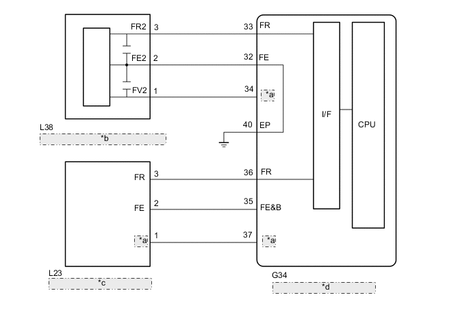
| *a | FV |
| *b | No. 2 Fuel Sender Gauge Assembly |
| *c | Fuel Sender Gauge Assembly |
| *d | Combination Meter Assembly |
CAUTION / NOTICE / HINT
CAUTION:
Be careful of flames.
Note
-
After turning the engine switch off, waiting time may be required before disconnecting the cable from the negative (-) battery terminal. Therefore, make sure to read the disconnecting the cable from the negative (-) battery terminal notices before proceeding with work.
-
When replacing the combination meter assembly, always replace it with a new one. If a combination meter assembly which was installed to another vehicle is used, the information stored in it will not match the information from the vehicle and a DTC may be stored.
PROCEDURE
-
CHECK FOR DTC
-
Check DTCs are output.
Body Electrical > Combination Meter > Trouble CodesOK DTCs are not output. Result Proceed to OK NG
NG 
GO TO DIAGNOSTIC TROUBLE CODE CHART Click here
OK 
-
-
CHECK FOR DTC (SFI SYSTEM)
-
Check if SFI system DTCs are output.
w/ Canister Pump Module:
w/o Canister Pump Module:
Powertrain > Engine > Trouble CodesOK SFI system DTCs are not output. Result Proceed to OK NG
NG
GO TO SFI SYSTEM w/ Canister Pump Module: GO TO SFI SYSTEM Click here
GO TO SFI SYSTEM w/o Canister Pump Module: GO TO SFI SYSTEM Click hereOK
-
-
PERFORM ACTIVE TEST USING GTS
-
Connect the GTS to the DLC3.
-
Turn the engine switch on (IG).
-
Turn the GTS on.
-
Enter the following menus: Body Electrical / Combination Meter / Active Test.
-
Perform the Active Test according to the display on the GTS.
Body Electrical > Combination Meter > Active TestTester Display Measurement Item Control Range Fuel Gauge Operation (Sender E) Fuel receiver gauge (Sender E) ON Fuel Gauge Operation (Empty) Fuel receiver gauge (Empty) ON Fuel Gauge Operation (Warning) Fuel receiver gauge (Warning) ON Fuel Gauge Operation (1/4) Fuel receiver gauge (1/4) ON Fuel Gauge Operation (1/2) Fuel receiver gauge (1/2) ON Fuel Gauge Operation (3/4) Fuel receiver gauge (3/4) ON Fuel Gauge Operation (Full) Fuel receiver gauge (Full) ON Fuel Gauge Operation (Sender F) Fuel receiver gauge (Sender F) ON
Body Electrical > Combination Meter > Active TestTester Display Fuel Gauge Operation (Sender E)
Body Electrical > Combination Meter > Active TestTester Display Fuel Gauge Operation (Empty)
Body Electrical > Combination Meter > Active TestTester Display Fuel Gauge Operation (Warning)
Body Electrical > Combination Meter > Active TestTester Display Fuel Gauge Operation (1/4)
Body Electrical > Combination Meter > Active TestTester Display Fuel Gauge Operation (1/2)
Body Electrical > Combination Meter > Active TestTester Display Fuel Gauge Operation (3/4)
Body Electrical > Combination Meter > Active TestTester Display Fuel Gauge Operation (Full)
Body Electrical > Combination Meter > Active TestTester Display Fuel Gauge Operation (Sender F) OK Fuel receiver gauge indication is normal. Result Proceed to OK NG
NG
REPLACE COMBINATION METER ASSEMBLY Click here
OK
-
-
INSPECT FUEL SENDER GAUGE ASSEMBLY
-
Remove the fuel sender gauge assembly.
-
Inspect the fuel sender gauge assembly.
Result Result Proceed to OK A NG (for Fuel suction gauge assembly) B NG (for No. 2 fuel sender gauge assembly) C
A
CLEAN INSIDE OF FUEL TANK ASSEMBLY
B
REPLACE FUEL SENDER GAUGE ASSEMBLY Click here
C
REPLACE NO. 2 FUEL SENDER GAUGE ASSEMBLY Click here
-