LIGHTING SYSTEM(w/o Automatic Headlight Beam Level Control System) LO-beam Headlight does not Illuminate
DESCRIPTION
The main body ECU (multiplex network body ECU) controls the low beam headlights.
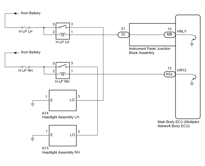
WIRING DIAGRAM
-
HEADLIGHT ASSEMBLY CIRCUIT
CAUTION / NOTICE / HINT
Note
-
Inspect the fuses for circuits related to this system before performing the following procedure.
-
Before replacing the main body ECU (multiplex network body ECU), refer to Service Bulletin.*
-
*: w/ Smart Entry and Start System
PROCEDURE
-
PERFORM ACTIVE TEST USING GTS
-
Connect the GTS to the DLC3.
-
Turn the ignition switch to ON.
-
Turn the GTS on.
-
Enter the following menus: Body Electrical / Main Body / Active Test.
-
Perform the Active Test according to the display on the GTS.
Body Electrical > Main Body > Active TestTester Display Measurement Item Control Range Diagnostic Note Headlight Relay Low beam headlights OFF or ON -
Body Electrical > Main Body > Active TestTester Display Headlight Relay OK Low beam headlights illuminate. Result Result Proceed to OK A NG (for LH Side) B NG (for RH Side) C
A 
PROCEED TO NEXT SUSPECTED AREA SHOWN IN PROBLEM SYMPTOMS TABLE Click here
C 
INSPECT HEADLIGHT ASSEMBLY RH (LO TERMINAL VOLTAGE) Click here
B 
-
-
INSPECT HEADLIGHT ASSEMBLY LH (LO TERMINAL VOLTAGE)
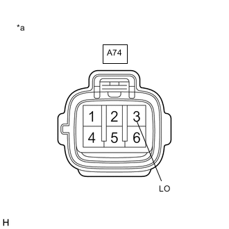
*a Front view of wire harness connector
(to Headlight Assembly LH)
-
Disconnect the A74 headlight assembly LH connector.
-
Measure the voltage according to the value(s) in the table below.
Standard Voltage Tester Connection Condition Specified Condition A74-3 (LO) - Body ground Light control switch in head position 11 to 14 V Result Proceed to OK NG
NG
CHECK HARNESS AND CONNECTOR (H-LP LH RELAY - HEADLIGHT ASSEMBLY LH) Click here
OK
-
-
CHECK HARNESS AND CONNECTOR (HEADLIGHT ASSEMBLY LH - BODY GROUND)
-
Measure the resistance according to the value(s) in the table below.
Standard Resistance Tester Connection Condition Specified Condition A74-1 (E) - Body ground Always Below 1 Ω Result Proceed to OK NG
NG
REPAIR OR REPLACE HARNESS OR CONNECTOR
OK
-
-
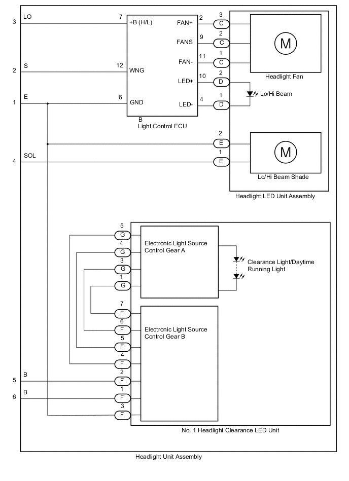
INSPECT HEADLIGHT UNIT ASSEMBLY LH
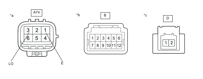
*a Component without harness connected
(to Wire Harness)
*b Component without harness connected
(to Light Control ECU)
*c Component without harness connected
(to Headlight LED Unit Assembly LH)
- -
-
Remove the headlight assembly LH.
-
Remove the headlight unit assembly LH.
-
Measure the resistance according to the value(s) in the table below.
Standard Resistance Tester Connection Condition Specified Condition A74-1 (E) - B-6 Always Below 1 Ω A74-3 (LO) - B-7 Always Below 1 Ω B-4 - D-1 Always Below 1 Ω B-10 - D-2 Always Below 1 Ω Result Proceed to OK NG
NG
REPLACE HEADLIGHT UNIT ASSEMBLY LH Click here
OK
-
-
CHECK LIGHT CONTROL ECU
-
Remove each light control ECU, interchange the light control ECU (for LH) with (for RH) and connect the connectors.
Result Proceed to NEXT
NEXT
-
-
CHECK OPERATION (LOW BEAM HEADLIGHT)
-
Check that the low beam headlight operates normally.
OK Low beam headlight operates normally. Result Proceed to OK NG
OK
REPLACE HEADLIGHT LED UNIT ASSEMBLY LH Click here
NG
REPLACE LIGHT CONTROL ECU Click here
-
-
CHECK HARNESS AND CONNECTOR (H-LP LH RELAY - HEADLIGHT ASSEMBLY LH)
-
Remove the H-LP LH relay.
-
Measure the resistance according to the value(s) in the table below.
Standard Resistance Tester Connection Condition Specified Condition 3 (H-LP LH relay) - A74-3 (LO) Always Below 1 Ω 3 (H-LP LH relay) or A74-3 (LO) - Body ground Always 10 kΩ or higher Result Proceed to OK NG
NG
REPAIR OR REPLACE HARNESS OR CONNECTOR
OK
-
-
INSPECT H-LP LH RELAY
-
Inspect the H-LP LH relay.
Result Proceed to OK NG
NG
REPLACE H-LP LH RELAY
OK
-
-
CHECK HARNESS AND CONNECTOR (POWER SOURCE - H-LP LH RELAY)
-
Measure the voltage according to the value(s) in the table below.
Standard Voltage Tester Connection Condition Specified Condition 2 (H-LP LH relay) - Body ground Always 11 to 14 V 5 (H-LP LH relay) - Body ground Always 11 to 14 V Result Proceed to OK NG
NG
REPAIR OR REPLACE HARNESS OR CONNECTOR
OK
-
-
CHECK HARNESS AND CONNECTOR (H-LP LH RELAY - INSTRUMENT PANEL JUNCTION BLOCK ASSEMBLY)
-
Disconnect the 3C instrument panel junction block assembly connector.
-
Measure the resistance according to the value(s) in the table below.
Standard Resistance Tester Connection Condition Specified Condition 1 (H-LP LH relay) - 3C-31 Always Below 1 Ω 1 (H-LP LH relay) or 3C-31 - Body ground Always 10 kΩ or higher Result Proceed to OK NG
NG
REPAIR OR REPLACE HARNESS OR CONNECTOR
OK
-
-
INSPECT INSTRUMENT PANEL JUNCTION BLOCK ASSEMBLY
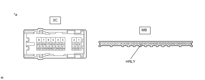
*a Component without harness connected
(Instrument Panel Junction Block Assembly)
- -
-
Remove the instrument panel junction block assembly.
-
Remove the main body ECU (multiplex network body ECU) from the instrument panel junction block assembly.
-
Measure the resistance according to the value(s) in the table below.
Standard Resistance Tester Connection Condition Specified Condition 3C-31 - MB-15 (HRLY) Always Below 1 Ω Result Proceed to OK NG
OK
REPLACE MAIN BODY ECU (MULTIPLEX NETWORK BODY ECU) Click here
NG
REPLACE INSTRUMENT PANEL JUNCTION BLOCK ASSEMBLY Click here
-
-
INSPECT HEADLIGHT ASSEMBLY RH (LO TERMINAL VOLTAGE)

*a Front view of wire harness connector
(to Headlight Assembly RH)
-
Disconnect the A73 headlight assembly RH connector.
-
Measure the voltage according to the value(s) in the table below.
Standard Voltage Tester Connection Condition Specified Condition A73-3 (LO) - Body ground Light control switch in head position 11 to 14 V Result Proceed to OK NG
NG
CHECK HARNESS AND CONNECTOR (H-LP RH RELAY - HEADLIGHT ASSEMBLY RH) Click here
OK
-
-
CHECK HARNESS AND CONNECTOR (HEADLIGHT ASSEMBLY RH - BODY GROUND)
-
Measure the resistance according to the value(s) in the table below.
Standard Resistance Tester Connection Condition Specified Condition A73-1 (E) - Body ground Always Below 1 Ω Result Proceed to OK NG
NG
REPAIR OR REPLACE HARNESS OR CONNECTOR
OK
-
-
INSPECT HEADLIGHT UNIT ASSEMBLY RH
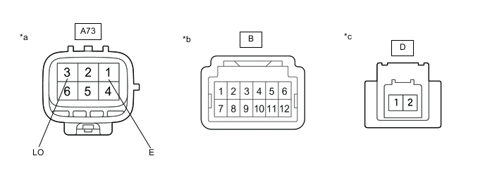
*a Component without harness connected
(to Wire Harness)
*b Component without harness connected
(to Light Control ECU)
*c Component without harness connected
(to Headlight LED Unit Assembly RH)
- -
-
Remove the headlight assembly RH.
-
Remove the headlight unit assembly RH.
-
Measure the resistance according to the value(s) in the table below.
Standard Resistance Tester Connection Condition Specified Condition A73-1 (E) - B-6 Always Below 1 Ω A73-3 (LO) - B-7 Always Below 1 Ω B-4 - D-1 Always Below 1 Ω B-10 - D-2 Always Below 1 Ω Result Proceed to OK NG
NG
REPLACE HEADLIGHT UNIT ASSEMBLY RH Click here
OK
-
-
CHECK LIGHT CONTROL ECU
-
Remove each light control ECU, interchange the light control ECU (for RH) with (for LH) and connect the connectors.
Result Proceed to NEXT
NEXT
-
-
CHECK OPERATION (LOW BEAM HEADLIGHT)
-
Check that the low beam headlight operates normally.
OK Low beam headlight operates normally. Result Proceed to OK NG
OK
REPLACE HEADLIGHT LED UNIT ASSEMBLY RH Click here
NG
REPLACE LIGHT CONTROL ECU Click here
-
-
CHECK HARNESS AND CONNECTOR (H-LP RH RELAY - HEADLIGHT ASSEMBLY RH)
-
Remove the H-LP RH relay.
-
Measure the resistance according to the value(s) in the table below.
Standard Resistance Tester Connection Condition Specified Condition 3 (H-LP RH relay) - A73-3 (LO) Always Below 1 Ω 3 (H-LP RH relay) or A73-3 (LO) - Body ground Always 10 kΩ or higher Result Proceed to OK NG
NG
REPAIR OR REPLACE HARNESS OR CONNECTOR
OK
-
-
INSPECT H-LP RH RELAY
-
Inspect the H-LP RH relay.
Result Proceed to OK NG
NG
REPLACE H-LP RH RELAY
OK
-
-
CHECK HARNESS AND CONNECTOR (POWER SOURCE - H-LP RH RELAY)
-
Measure the voltage according to the value(s) in the table below.
Standard Voltage Tester Connection Condition Specified Condition 2 (H-LP RH relay) - Body ground Always 11 to 14 V 5 (H-LP RH relay) - Body ground Always 11 to 14 V Result Proceed to OK NG
NG
REPAIR OR REPLACE HARNESS OR CONNECTOR
OK
-
-
CHECK HARNESS AND CONNECTOR (H-LP RH RELAY - MAIN BODY ECU (MULTIPLEX NETWORK BODY ECU))
-
Disconnect the K52 main body ECU (multiplex network body ECU) connector.
-
Measure the resistance according to the value(s) in the table below.
Standard Resistance Tester Connection Condition Specified Condition 1 (H-LP RH relay) - K52-12 (HRY2) Always Below 1 Ω 1 (H-LP RH relay) or K52-12 (HRY2) - Body ground Always 10 kΩ or higher Result Proceed to OK NG
OK
REPLACE MAIN BODY ECU (MULTIPLEX NETWORK BODY ECU) Click here
NG
REPAIR OR REPLACE HARNESS OR CONNECTOR
-