POWER STEERING ECU(for LHD) INSTALLATION
PROCEDURE
-
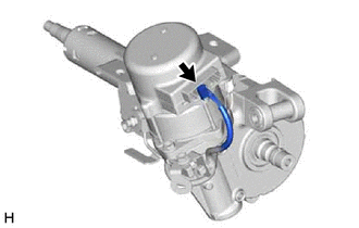
INSTALL ELECTRIC POWER STEERING MOTOR SHAFT DAMPER
-
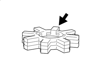

Grease Apply grease to a new electric power steering motor shaft damper.
Note
First wipe off the existing grease from the serrated part, and then apply the dedicated grease supplied with a new power steering ECU assembly or electric power steering column sub-assembly.
-
Install the electric power steering motor shaft damper to the electric power steering column sub-assembly.
-
-
INSTALL POWER STEERING ECU ASSEMBLY
Note
-
Do not drop the power steering ECU assembly, strike it with tools or subject it to impacts.
-
If the power steering ECU assembly is subjected to an impact, replace it with a new one.
-
Do not pull the wire harness of the electric power steering column sub-assembly.
-
Do not allow any moisture to come into contact with the power steering ECU assembly.
-
Do not loosen any bolts not mentioned in the procedure.
-
Do not allow any foreign matter to contaminate the power steering ECU assembly.
-
for Type A:
-
Using a T40 "TORX" socket wrench, temporarily install the power steering ECU assembly to the electric power steering column subassembly with the 2 screws.
Note
When temporarily installing the 2 screws to the power steering ECU assembly, do not tighten them all the way down.
-
-
for Type B:
-
Temporarily install the power steering ECU assembly to the electric power steering column sub-assembly with the 2 bolts.
Note
When temporarily installing the 2 bolts to the power steering ECU assembly, do not tighten them all the way down.
-
-
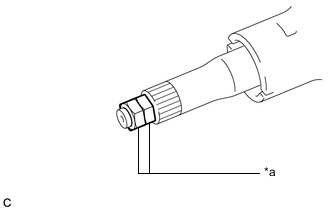
*a Service Nut Install 2 service nuts to the steering main shaft.
Recommended Service Nut Thread Diameter 12.0 mm (0.472 in.) Thread Pitch 1.25 mm (0.0492 in.) -
Simultaneously rotate the service nut that was installed first counterclockwise and rotate the service nut that was installed second clockwise to lock them.
Note
Do not apply excessive torque to the service nuts by using a tool such as an impact wrench.
Tech Tips
The service nuts are used for turning the steering main shaft during inspection of the steering main shaft rotating torque.
Remove the service nuts after performing this inspection.
-
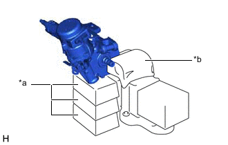
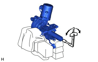
*a Wooden Block *b Cloth Secure the steering column assembly in a vise using aluminum plates, cloths and wooden blocks.
Note
-
Do not overtighten the vise, as the steering column assembly may become deformed.
-
Secure the power steering ECU assembly so that it is upright.
-
Support the steering column assembly with wooden blocks or similar items to ensure that it does not fall.
-
-
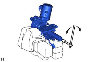
Rotate the steering main shaft 180 degrees counterclockwise and then 180 degrees clockwise at a speed of 60 rpm, and repeat 2 to 3 times to center the axis of the power steering ECU assembly. [*1]
-
for Type A:
-
Using a T40 "TORX" socket wrench, tighten the 2 screws. [*2]
- Torque:
- 18.5 N*m { 189 kgf*cm, 14 ft.*lbf }
-
-
for Type B:
-
Tighten the 2 bolts. [*2]
- Torque:
- 18.5 N*m { 189 kgf*cm, 14 ft.*lbf }
-
-
Using a torque wrench, measure the turning torque of the steering main shaft.
Preload 1.2 to 2.4 N*m (13 to 24 kgf*cm, 11 to 21 in.*lbf) Note
Ensure that there is no abnormal resistance during rotation.
If the turning torque is not as specified, loosen the 2 bolts and repeat steps [*1] and [*2] to recenter the axis of the power steering ECU assembly.
-
Remove the 2 service nuts.
-
Connect the connector.
-
-
INSTALL STEERING COLUMN ASSEMBLY
-
TORQUE SENSOR ZERO POINT CALIBRATION
-
ASSIST MAP WRITING