IMMOBILISER SYSTEM(w/o Entry and Start System) Engine does not Start but Initial Combustion Occurs
| DTC Code | DTC Name |
|---|---|
| Engine does not Start but Initial Combustion Occurs |
DESCRIPTION
If the key ID codes of the door control transmitter assembly and transponder key ECU assembly match, the immobiliser system is unset and the engine start permission signal is sent to the ECM. When the ID codes of the transponder key ECU assembly and ECM match, the engine starts.
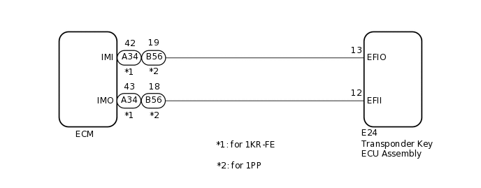
WIRING DIAGRAM
CAUTION / NOTICE / HINT
If the transponder key ECU assembly or ECM is replaced, refer to Service Bulletin.
PROCEDURE
CLEAR DTC
Clear the DTCs.
Body Electrical > Immobiliser > Clear DTCs
Powertrain > Engine and ECT > Clear DTCs
Result
Proceed to
NEXT
CHECK FOR DTC
Check for DTCs.
Body Electrical > Immobiliser > Trouble Codes
Powertrain > Engine and ECT > Trouble Codes
Result
Result
Proceed to
DTCs are not output
A
DTCs are output
B
CHECK WHETHER ENGINE STARTS
Using a registered door control transmitter assembly, turn the ignition switch to ON.
Check that the engine starts 5 seconds after the ignition switch was turned to ON.
OK
Engine starts normally.
Result
Result
Proceed to
Engine can be started
A
Engine cannot be started
B
CHECK ECM (TERMINAL IMI)
for 1KR-FE
Using an oscilloscope, check the waveform.
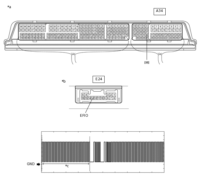
*a
Component with harness connected
(ECM)
*b
Component with harness connected
(Transponder Key ECU Assembly)
*c
Waveform
-
-
Table 1. OK Tester Connection
Condition
Tool Setting
Specified Condition
A34-42 (IMI) - E24-13 (EFIO)
Within 3 seconds of starter operation and initial combustion, or within 3 seconds of ignition switch first being turned to ON after cable disconnected and reconnected to negative (-) battery terminal
2 V/DIV., 500 ms./DIV.
Pulse generation
(See waveform)
for 1PP
Using an oscilloscope, check the waveform.
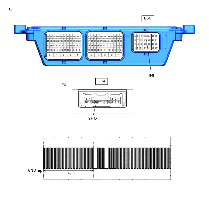
*a
Component with harness connected
(ECM)
*b
Component with harness connected
(Transponder Key ECU Assembly)
*c
Waveform
-
-
Table 2. OK Tester Connection
Condition
Tool Setting
Specified Condition
B56-19 (IMI) - E24-13 (EFIO)
Within 3 seconds of starter operation and initial combustion, or within 3 seconds of ignition switch first being turned to ON after cable disconnected and reconnected to negative (-) battery terminal
2 V/DIV., 500 ms./DIV.
Pulse generation
(See waveform)
Result
Result
Proceed to
Normal waveform
A
Waveform not output, or has abnormal wavelength or shape
B
B CHECK HARNESS AND CONNECTOR (TRANSPONDER KEY ECU ASSEMBLY - ECM)Click here
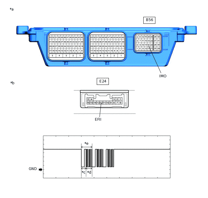
CHECK ECM (TERMINAL IMO)
for 1KR-FE
Using an oscilloscope, check the waveform.
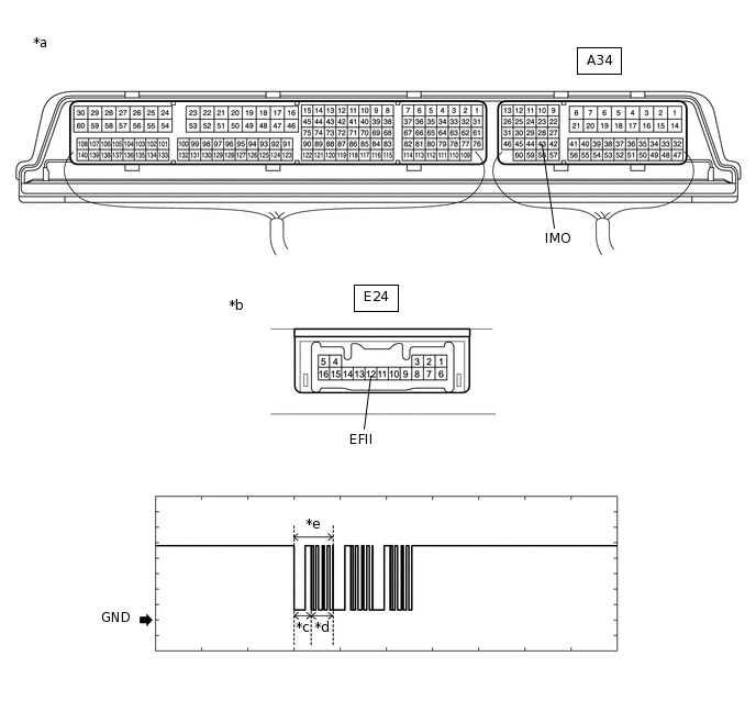
*a
Component with harness connected
(ECM)
*b
Component with harness connected
(Transponder Key ECU Assembly)
*c
Approximately 160 ms
*d
Approximately 270 ms
*e
Waveform
-
-
Table 3. OK Tester Connection
Condition
Tool Setting
Specified Condition
A34-43 (IMO) - E24-12 (EFII)
Within 3 seconds of starter operation and initial combustion, or within 3 seconds of ignition switch first being turned to ON after cable disconnected and reconnected to negative (-) battery terminal
2 V/DIV., 500 ms./DIV.
Pulse generation
(See waveform)
for 1PP
Using an oscilloscope, check the waveform.
*a
Component with harness connected
(ECM)
*b
Component with harness connected
(Transponder Key ECU Assembly)
*c
Approximately 160 ms
*d
Approximately 270 ms
*e
Waveform
-
-
Table 4. OK Tester Connection
Condition
Tool Setting
Specified Condition
B56-18 (IMO) - E24-12 (EFII)
Within 3 seconds of starter operation and initial combustion, or within 3 seconds of ignition switch first being turned to ON after cable disconnected and reconnected to negative (-) battery terminal
2 V/DIV., 500 ms./DIV.
Pulse generation
(See waveform)
Result
Result
Proceed to
Normal waveform
A
Waveform not output, or has abnormal wavelength or shape
B
CHECK ECM (TERMINAL IMI)
for 1KR-FE
Using an oscilloscope, check the waveform.
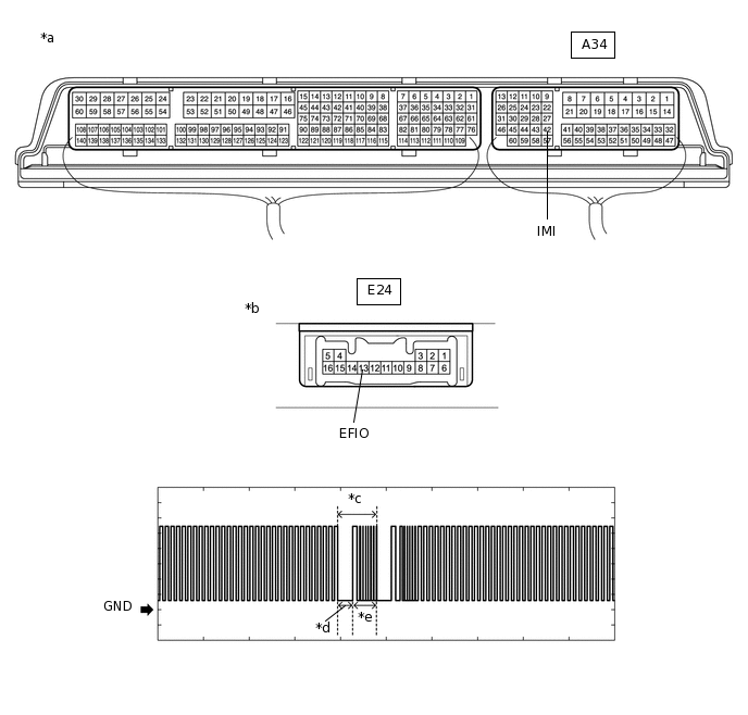
*a
Component with harness connected
(ECM)
*b
Component with harness connected
(Transponder Key ECU Assembly)
*c
Waveform
*d
Approximately 160 ms
*e
Approximately 270 ms
-
-
Item
Content
Terminal No. (Symbol)
A34-42 (IMI) - E24-13 (EFIO)
Tool Setting
2 V/DIV., 500 ms./DIV.
Condition
Within 3 seconds of starter operation and initial combustion, or within 3 seconds of ignition switch first being turned to ON after cable disconnected and reconnected to negative (-) battery terminal
for 1PP
Using an oscilloscope, check the waveform.
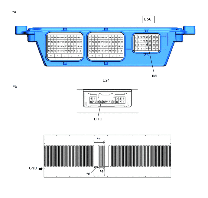
*a
Component with harness connected
(ECM)
*b
Component with harness connected
(Transponder Key ECU Assembly)
*c
Waveform
*d
Approximately 160 ms
*e
Approximately 270 ms
-
-
Item
Content
Terminal No. (Symbol)
B56-19 (IMI) - E24-13 (EFIO)
Tool Setting
2 V/DIV., 500 ms./DIV.
Condition
Within 3 seconds of starter operation and initial combustion, or within 3 seconds of ignition switch first being turned to ON after cable disconnected and reconnected to negative (-) battery terminal
Result
Result
Proceed to
Normal waveform
A
Waveform not output, or has abnormal wavelength or shape
B
B REPLACE TRANSPONDER KEY ECU ASSEMBLYClick here
REGISTER ECU COMMUNICATION ID
Register the communication ID between the transponder key ECU assembly and ECM.
Tip:Refer to Service Bulletin.
Result
Proceed to
NEXT
CHECK WHETHER ENGINE STARTS
Using a registered door control transmitter assembly, turn the ignition switch to ON.
Check that the engine starts 5 seconds after the ignition switch was turned to ON.
OK
Engine starts normally.
Result
Result
Proceed to
Engine can be started
A
Engine cannot be started
B
A END (REGISTERED COMMUNICATION ID WAS DEFECTIVE)
REPLACE TRANSPONDER KEY ECU ASSEMBLY
Replace the transponder key ECU assembly with a new one.
Tip:Refer to Service Bulletin.
Note:Key ID code registration is necessary when replacing the transponder key ECU assembly, refer to Service Bulletin.
Result
Proceed to
NEXT
CHECK WHETHER ENGINE STARTS
Using a registered door control transmitter assembly, turn the ignition switch to ON.
Check that the engine starts 5 seconds after the ignition switch was turned to ON.
OK
Engine starts normally.
Result
Result
Proceed to
Engine can be started
A
Engine cannot be started
B
A END (TRANSPONDER KEY ECU ASSEMBLY WAS DEFECTIVE)
CHECK HARNESS AND CONNECTOR (TRANSPONDER KEY ECU ASSEMBLY - ECM)
for 1KR-FE
Disconnect the E24 transponder key ECU assembly connector.
Disconnect the A34 ECM connector.
Measure the resistance according to the value(s) in the table below.
Standard Resistance
Tester Connection
Condition
Specified Condition
E24-13 (EFIO) - A34-42 (IMI)
Always
Below 1 Ω
A34-42 (IMI) or E24-13 (EFIO) - Body ground
Always
10 kΩ or higher
for 1PP
Disconnect the E24 transponder key ECU assembly connector.
Disconnect the B56 ECM connector.
Measure the resistance according to the value(s) in the table below.
Standard Resistance
Tester Connection
Condition
Specified Condition
E24-13 (EFIO) - B56-19 (IMI)
Always
Below 1 Ω
B56-19 (IMI) or E24-13 (EFIO) - Body ground
Always
10 kΩ or higher
Result
Proceed to
OK
NG
OK REPLACE TRANSPONDER KEY ECU ASSEMBLY
NG REPAIR OR REPLACE HARNESS OR CONNECTOR