LIGHTING SYSTEM Turn Signal Switch Circuit
| DTC Code | DTC Name |
|---|---|
| Turn Signal Switch Circuit |
DESCRIPTION
The combination meter receives the turn signal switch information and controls the turn signal lights.
WIRING DIAGRAM
PROCEDURE
READ VALUE USING GTS (TURN SIGNAL SWITCH)
Using the GTS, read the Data List.
Body Electrical > Combination Meter > Data List
Tester Display
Measurement Item
Range
Normal Condition
Diagnostic Note
Turn Signal Switch (Right)
Headlight dimmer switch (turn signal switch) right turn position signal
ON or OFF
ON: Headlight dimmer switch (turn signal switch) in right turn position
OFF: Headlight dimmer switch (turn signal switch) not in right turn position
-
Turn Signal Switch (Left)
Headlight dimmer switch (turn signal switch) left turn position signal
ON or OFF
ON: Headlight dimmer switch (turn signal switch) in left turn position
OFF: Headlight dimmer switch (turn signal switch) not in left turn position
-
Body Electrical > Combination Meter > Data List
Tester Display
Turn Signal Switch (Right)
Turn Signal Switch (Left)
OK
The display is as specified in the normal condition column.
Result
Proceed to
OK
NG
INSPECT HEADLIGHT DIMMER SWITCH ASSEMBLY
Remove the headlight dimmer switch assembly.
Inspect the headlight dimmer switch assembly.
Result
Proceed to
OK
NG
CHECK HARNESS AND CONNECTOR (HEADLIGHT DIMMER SWITCH ASSEMBLY - COMBINATION METER ASSEMBLY AND BODY GROUND)
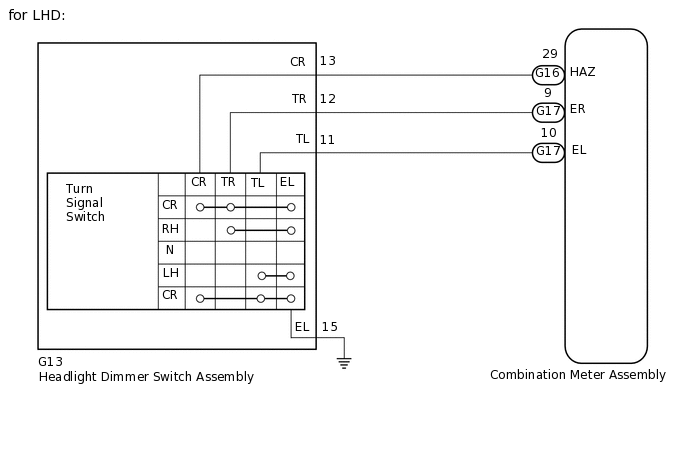
for LHD:
Disconnect the G13 headlight dimmer switch assembly connector.
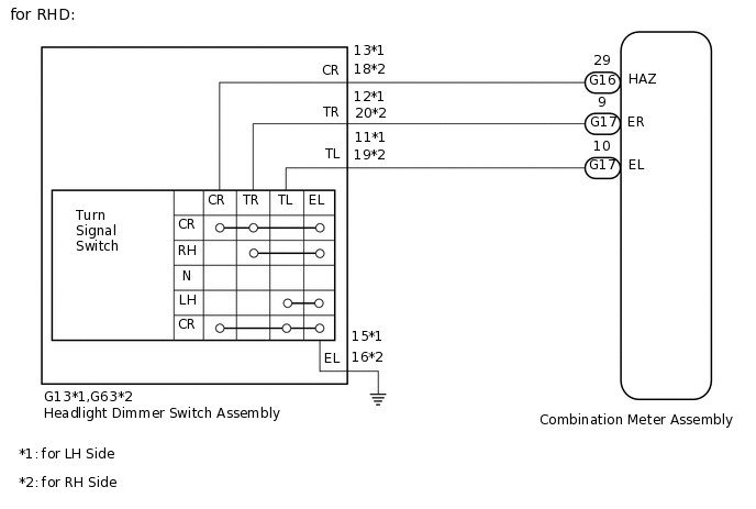
for RHD:
Disconnect the G13*1 or G63*2 headlight dimmer switch assembly connector.
*1: for LH Side
*2: for RH Side
Disconnect the G16 and G17 combination meter assembly connectors.
Measure the resistance according to the value(s) in the table below.
Standard Resistance
for LHD
Tester Connection
Condition
Specified Condition
G16-29 (HAZ) - G13-13 (CR)
Always
Below 1 Ω
G17-9 (ER) - G13-12 (TR)
G17-10 (EL) - G13-11 (TL)
G13-15 (EL) - Body ground
G16-29 (HAZ) - Body ground
Always
10 kΩ or higher
G17-9 (ER) - Body ground
G17-10 (EL) - Body ground
for RHD
Tester Connection
Condition
Specified Condition
G16-29 (HAZ) - G13-13 (CR)*1
Always
Below 1 Ω
G16-29 (HAZ) - G63-18 (CR)*2
G17-9 (ER) - G13-12 (TR)*1
G17-9 (ER) - G63-20 (TR)*2
G17-10 (EL) - G13-11 (TL)*1
G17-10 (EL) - G63-19 (TL)*2
G13-15 (EL) - Body ground*1
G63-16 (EL) - Body ground*2
G16-29 (HAZ) - Body ground
Always
10 kΩ or higher
G17-9 (ER) - Body ground
G17-10 (EL) - Body ground
*1: for LH Side
*2: for RH Side
Result
Proceed to
OK
NG
NG REPAIR OR REPLACE HARNESS OR CONNECTOR