DYNAMIC RADAR CRUISE CONTROL SYSTEM Cruise Control Switch Circuit
| DTC Code | DTC Name |
|---|---|
| Cruise Control Switch Circuit |
DESCRIPTION
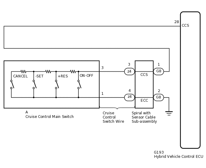
This circuit sends a signal to the hybrid vehicle control ECU depending on the cruise control main switch condition. The battery supplies positive (+) battery voltage to the circuit control switch. Then terminal CCS of the hybrid vehicle control ECU receives the voltage according to the switch condition.
WIRING DIAGRAM
PROCEDURE
READ VALUE USING TECHSTREAM
Check the Data List for proper functioning of the cruise control main switch.
Powertrain > Radar Cruise1 > Data List
Tester Display
Measurement Item
Range
Normal Condition
Diagnostic Note
Cancel Switch
CANCEL switch status
ON or OFF
ON: CANCEL switch on
OFF: CANCEL switch off
-
-SET Switch
-SET switch status
ON or OFF
ON: -SET switch on
OFF: -SET switch off
-
+RES Switch
+RES switch status
ON or OFF
ON: +RES switch on
OFF: +RES switch off
-
Cruise Ready Main-CPU
Cruise control system standby condition
ON or OFF
Each time cruise control main switch is pushed, ON or OFF changes
-
Cruise Ready Sub-CPU
Cruise control system standby condition
ON or OFF
Each time cruise control main switch is pushed, ON or OFF changes
-
Powertrain > Radar Cruise1 > Data List
Tester Display
Cancel Switch
-SET Switch
+RES Switch
Cruise Ready Main-CPU
Cruise Ready Sub-CPU
OK
When the cruise control main switch is operated, the display changes as shown above.
Result
Proceed to
OK
NG
INSPECT CRUISE CONTROL MAIN SWITCH
Remove the cruise control main switch.
Inspect the cruise control main switch.
Result
Proceed to
OK
NG
CHECK CRUISE CONTROL SWITCH WIRE
-
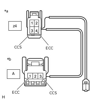
*a
Front view of wire harness connector
(to Spiral with Sensor Cable Sub-assembly)
*b
Front view of wire harness connector
(to Cruise Control Main Switch)
Disconnect the z4 spiral with sensor cable sub-assembly connector.
Disconnect the A cruise control switch wire connector.
Measure the resistance according to the value(s) in the table below.
Standard Resistance
Tester Connection
Condition
Specified Condition
z4-3 (CCS) - A-3 (CCS)
Always
Below 1 Ω
z4-4 (ECC) - A-1 (ECC)
Always
Below 1 Ω
z4-3 (CCS) or A-3 (CCS) - Body ground
Always
10 kΩ or higher
z4-4 (ECC) or A-1 (ECC) - Body ground
Always
10 kΩ or higher
Result
Proceed to
OK
NG
NG REPLACE CRUISE CONTROL SWITCH WIRE
-
INSPECT SPIRAL WITH SENSOR CABLE SUB-ASSEMBLY
Remove the spiral with sensor cable sub-assembly.
for Single Type
for Dual Type
Inspect the spiral with sensor cable sub-assembly.
for Single Type
for Dual Type
Result
Proceed to
OK
NG
CHECK HARNESS AND CONNECTOR (SPIRAL WITH SENSOR CABLE SUB-ASSEMBLY - HYBRID VEHICLE CONTROL ECU AND BODY GROUND)
Disconnect the G8 spiral with sensor cable sub-assembly connector.
Disconnect the G193 hybrid vehicle control ECU connector.
Measure the resistance according to the value(s) in the table below.
Standard Resistance
Tester Connection
Condition
Specified Condition
G8-1 (CCS) - G193-28 (CCS)
Always
Below 1 Ω
G8-2 (ECC) - Body ground
Always
Below 1 Ω
G8-1 (CCS) or G193-28 (CCS) - Body ground
Always
10 kΩ or higher
Result
Proceed to
OK
NG
NG REPAIR OR REPLACE HARNESS OR CONNECTOR