ENGINE ASSEMBLY INSTALLATION
CAUTION / NOTICE / HINT
As the engine assembly with transaxle assembly is extremely heavy, the engine lifter may suddenly drop if the instructions listed in the repair manual are not followed. Therefore, always follow the instructions listed in the repair manual when performing this procedure.
PROCEDURE
INSTALL ENGINE MOUNTING INSULATOR LH
Tip:Perform this procedure only when replacement of the engine mounting insulator LH is necessary.
Install the engine mounting insulator LH with the 4 bolts.
95 N*m
969 kgf*cm
70 ft.*lbf
INSTALL ENGINE MOUNTING BRACKET LH
Tip:Perform this procedure only when replacement of the engine mounting bracket LH is necessary.
Apply adhesive to 2 to 3 threads at the end of each bolts.
Adhesive
Toyota Genuine Adhesive 1324, Three Bond 1324 or equivalent
Install the engine mounting bracket LH with the 4 bolts.
64 N*m
653 kgf*cm
47 ft.*lbf
INSTALL REAR ENGINE MOUNTING INSULATOR
Install the rear engine mounting insulator with the 2 bolts and 2 nuts.
95 N*m
969 kgf*cm
70 ft.*lbf
INSTALL FRONT ENGINE MOUNTING INSULATOR
Install the front engine mounting insulator to the front crossmember sub-assembly with the 2 bolts.
95 N*m
969 kgf*cm
70 ft.*lbf
REMOVE ENGINE FROM ENGINE STAND
Note:Pay attention to the angle of the sling device as the engine assembly or engine hangers may be damaged or deformed if the angle is incorrect.
With the exception of installing the engine assembly to an engine stand or removing the engine assembly from an engine stand, do not perform any work on the engine assembly while it is suspended, as doing so is dangerous.
Install a sling device and chain block to the engine assembly and hang the engine assembly.
Remove the engine assembly from the engine stand.
INSTALL MANUAL TRANSAXLE ASSEMBLY
INSTALL REAR ENGINE MOUNTING BRACKET
Install the rear engine mounting bracket with the 5 bolts.
45 N*m
459 kgf*cm
33 ft.*lbf
INSTALL FRONT ENGINE MOUNTING BRACKET
Install the front engine mounting bracket with the 4 bolts.
64 N*m
653 kgf*cm
47 ft.*lbf
INSTALL STARTER ASSEMBLY
INSTALL NO. 1 AIR TUBE ASSEMBLY
Install the No. 1 air tube assembly to the manual transaxle assembly with the 2 bolts.
20 N*m
204 kgf*cm
15 ft.*lbf
Connect the No. 4 water by-pass hose to the EGR cooler assembly.
Connect the compressor outlet elbow to the turbocharger sub-assembly.
INSTALL ENGINE WIRE
Connect the connectors, attach the clamps and install the engine wire to the engine assembly with the bracket bolts.
INSTALL REAR ENGINE MOUNTING INSULATOR
Install the rear engine mounting insulator with the bolt.
95 N*m
969 kgf*cm
70 ft.*lbf
INSTALL ENGINE WITH TRANSAXLE
Place the engine assembly on an engine lifter, and then remove the sling device and chain block from the engine assembly.
Note:Place wooden blocks or plate lift attachments so that the engine assembly is level.
With the exception of installing the engine assembly to an engine stand or removing the engine assembly from an engine stand, do not perform any work on the engine while it is suspended, as doing so is dangerous.
Never install attachments to the oil pan sub-assembly of the engine assembly or transaxle assembly as doing so may deform the oil pan sub-assembly.
Using the engine lifter, slowly raise the engine assembly and install it to the vehicle, and then install the intermediate shaft to the pinion.
CAUTION:Do not raise the engine assembly more than necessary. If the engine assembly is raised excessively, the vehicle may also be lifted up.
Note:Make sure that the engine assembly is clear of all wiring and hoses.
While raising the engine assembly into the vehicle, do not allow it to contact the vehicle.
Align the matchmarks on the intermediate shaft and pinion.
Temporarily install the front suspension crossmember sub-assembly with the 2 bolts.
Temporarily install the front suspension rear brace RH and front suspension rear brace LH with the 6 bolts.
Connect the front engine mounting insulator with the through bolt and nut.
145 N*m
1479 kgf*cm
107 ft.*lbf
Connect the engine mounting insulator LH with the bolt and nut.
56 N*m
571 kgf*cm
41 ft.*lbf
Tip:While holding the bolt in place, tighten the nut.
-
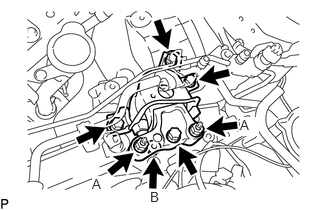
Install the engine mounting insulator RH with the 4 bolts and 3 nuts.
for bolt and nut A
95 N*m
969 kgf*cm
70 ft.*lbf
for nut B
52 N*m
530 kgf*cm
38 ft.*lbf
Attach the clamp and connect the air conditioner tube and accessory assembly.
Attach the 2 clamps and connect the suction pipe sub-assembly.
-
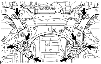
Tighten the 8 front suspension crossmember sub-assembly and front suspension member rear brace bolts.
for bolt A
137 N*m
1397 kgf*cm
101 ft.*lbf
for bolt B
93 N*m
948 kgf*cm
69 ft.*lbf
Install the front crossmember sub-assembly with the 4 bolts.
99 N*m
1010 kgf*cm
73 ft.*lbf
Connect the cable bracket with the bolt.
5.0 N*m
51 kgf*cm
44 in.*lbf
INSTALL FRONT SUSPENSION MEMBER REINFORCEMENT RH
-
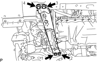
Install the front suspension member reinforcement RH with the 4 bolts.
99 N*m
1010 kgf*cm
73 ft.*lbf
Note:Tighten the bolts in the order shown in the illustration.
-
INSTALL FRONT SUSPENSION MEMBER REINFORCEMENT LH
-
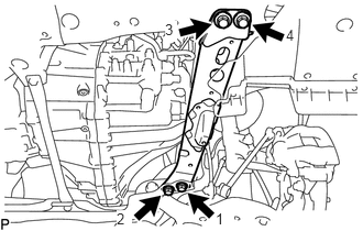
Install the front suspension member reinforcement LH with the 4 bolts.
99 N*m
1010 kgf*cm
73 ft.*lbf
Note:Tighten the bolts in the order shown in the illustration.
-
INSTALL FRONT LOWER ENGINE MOUNTING BRACKET REINFORCEMENT
Install the front lower engine mounting bracket reinforcement with the 2 bolts.
99 N*m
1010 kgf*cm
73 ft.*lbf
INSTALL FRONT DRIVE SHAFT HOLE SNAP RING LH
INSTALL FRONT DRIVE SHAFT ASSEMBLY LH
INSTALL FRONT DRIVE SHAFT ASSEMBLY RH
INSTALL FRONT AXLE ASSEMBLY LH
INSTALL FRONT AXLE ASSEMBLY RH
Tip:Perform the same procedure as for the LH side.
CONNECT FRONT STABILIZER LINK ASSEMBLY LH
CONNECT FRONT STABILIZER LINK ASSEMBLY RH
Tip:Perform the same procedure as for the LH side.
INSTALL FRONT AXLE SHAFT NUT LH
INSTALL FRONT AXLE SHAFT NUT RH
Tip:Perform the same procedure as for the LH side.
STAKE FRONT AXLE SHAFT NUT LH
STAKE FRONT AXLE SHAFT NUT RH
Tip:Perform the same procedure as for the LH side.
INSTALL NO. 1 STEERING COLUMN HOLE COVER SUB-ASSEMBLY
CONNECT NO. 2 STEERING INTERMEDIATE SHAFT ASSEMBLY
INSTALL COLUMN HOLE COVER SILENCER SHEET
CONNECT CLUTCH RELEASE CYLINDER ASSEMBLY
Connect the clutch release cylinder assembly and clutch flexible hose bracket with the 4 bolts.
12 N*m
122 kgf*cm
9 ft.*lbf
CONNECT TRANSMISSION CONTROL CABLE ASSEMBLY
Connect the 2 transmission control cable assemblies to the transmission control cable bracket with 2 new clips.
Connect the 2 transmission control cable assemblies to the manual transaxle assembly with the 2 pins.
INSTALL AIR CLEANER BRACKET
Install the air cleaner bracket with the 3 bolts.
7.0 N*m
71 kgf*cm
62 in.*lbf
INSTALL FUEL FILTER SUPPORT
Install the fuel filter support with the 3 bolts.
18 N*m
178 kgf*cm
13 ft.*lbf
Attach the clamp to connect the wire harness.
Attach the 2 clamps and connect the engine wire.
Connect the connector.
-
Connect the ECM connector and lower the lever.
Note:When connecting the ECM connector, make sure that dirt, water and other foreign matter is not stuck between the ECM connector and ECM.
Make sure that the lever is securely lowered.
INSTALL FUEL FILTER ASSEMBLY
CONNECT HOSES AND CONNECTORS
Connect the ground cable with the bolt.
13 N*m
127 kgf*cm
9 ft.*lbf
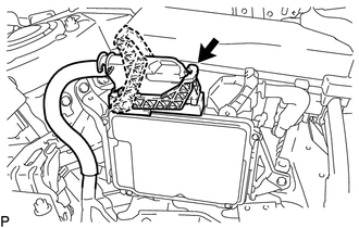
Connect the 2 connectors, attach the 2 claws to install the No. 1 engine room relay block and install the 2 nuts.
8.4 N*m
86 kgf*cm
74 in.*lbf
Install the No. 1 engine room relay block cover.
CONNECT INLET HEATER WATER HOSE
Connect the inlet heater water hose to the No. 1 air tube assembly, and slide the clamp to secure the hose.
CONNECT WATER HOSE SUB-ASSEMBLY
Connect the water hose to the No. 1 air tube assembly, and slide the clamp to secure the hose.
CONNECT NO. 2 FUEL HOSE
Connect the No. 2 fuel hose to the fuel feed pipe sub-assembly, and slide the clamp to secure the hose.
CONNECT FUEL HOSE
Connect the fuel hose to the fuel feed pipe sub-assembly, and slide the clamp to secure the hose.
CONNECT VACUUM HOSE
Connect the vacuum hose to the No. 2 vacuum hose assembly, and slide the clamp to secure the hose.
INSTALL RADIATOR HOSE SUB-ASSEMBLY
Install the radiator hose sub-assembly to the outlet.
Connect the radiator hose sub-assembly, and slide the clamp to secure the hose.
INSTALL WATER BY-PASS HOSE ASSEMBLY
Connect the water by-pass hose assembly to the water by-pass pipe.
Connect the water by-pass hose assembly to the No. 1 air tube assembly, and slide the clamp to secure the hose.
INSTALL RADIATOR RESERVOIR ASSEMBLY
Install the radiator reservoir assembly with the 2 bolts.
5.0 N*m
51 kgf*cm
44 in.*lbf
Connect the No. 2 water by-pass hose assembly to the radiator reservoir assembly, and slide the clamp to secure the hose.
Connect the water by-pass hose assembly to the radiator reservoir assembly, and slide the clamp to secure the hose.
INSTALL AIR CLEANER CASE SUB-ASSEMBLY
INSTALL AIR CLEANER FILTER ELEMENT SUB-ASSEMBLY
INSTALL AIR CLEANER CAP SUB-ASSEMBLY WITH AIR CLEANER HOSE ASSEMBLY
CONNECT DISCHARGE HOSE SUB-ASSEMBLY (w/ Air Conditioning System)
CONNECT SUCTION HOSE SUB-ASSEMBLY (w/ Air Conditioning System)
INSTALL RADIATOR ASSEMBLY
INSTALL BATTERY CARRIER
INSTALL BATTERY TRAY
INSTALL BATTERY
INSTALL BATTERY INSULATOR
INSTALL BATTERY CLAMP SUB-ASSEMBLY
INSTALL FRONT EXHAUST PIPE ASSEMBLY
ADD MANUAL TRANSAXLE OIL
ADD ENGINE OIL
ADD ENGINE COOLANT
INSTALL FRONT BUMPER COVER
INSTALL OUTER COWL TOP PANEL
Install the outer cowl top panel with the 9 bolts.
12 N*m
122 kgf*cm
9 ft.*lbf
INSTALL FRONT WIPER MOTOR AND LINK ASSEMBLY
CONNECT CABLE TO POSITIVE BATTERY TERMINAL
CONNECT CABLE TO NEGATIVE BATTERY TERMINAL
Note:When disconnecting the cable, some systems need to be initialized after the cable is reconnected (Click here).
CHARGE REFRIGERANT (for HFC-134a(R134a))
CHARGE REFRIGERANT (for HFO-1234yf(R1234yf))
PERFORM REGISTRATION
WARM UP ENGINE (w/ Air Conditioning System)
INSPECT FOR REFRIGERANT LEAK (for HFC-134a(R134a))
INSPECT FOR REFRIGERANT LEAK (for HFO-1234yf(R1234yf))
INSPECT FOR OIL LEAK
INSPECT FOR COOLANT LEAK
INSPECT FOR FUEL LEAK
INSPECT FOR EXHAUST GAS LEAK
INSTALL REAR ENGINE UNDER COVER RH
Install the rear engine under cover RH with the 5 clips.
INSTALL REAR ENGINE UNDER COVER LH
Install the rear engine under cover LH with the 5 clips.
INSTALL NO. 2 ENGINE UNDER COVER
INSTALL NO. 1 ENGINE UNDER COVER
INSTALL FRONT LOWER BUMPER ABSORBER
INSTALL NO. 1 ENGINE COVER
CHECK IDLE SPEED
CHECK MAXIMUM ENGINE SPEED
INSTALL RADIATOR SUPPORT OPENING COVER
Attach the 4 hooks and install the radiator support opening cover.
Install the 3 clips.
ADJUST FRONT WHEEL ALIGNMENT
CHECK ABS SPEED SENSOR SIGNAL