FRONT STABILIZER BAR INSTALLATION
PROCEDURE
-
INSTALL FRONT STABILIZER BAR BUSHING LH
-
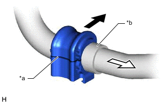
*a Cutout *b Stopper 
Front of the Vehicle 
Inside of the Vehicle Install the front stabilizer bar bushing LH to the front stabilizer bar as shown in the illustration.
Note
-
Install the front stabilizer bar bushing LH so that the cutout is facing the rear of the vehicle.
-
Install the front stabilizer bar bushing LH onto the front stabilizer bar so that the stopper ring of the front stabilizer bar faces the outside of the vehicle.
-
-
-
INSTALL FRONT STABILIZER BAR BUSHING RH
-
w/ front stabilizer bar protector:
-
Install the front stabilizer bar protector to the front stabilizer bar.
Dimension (A) 0 to 5 mm (0 to 0.1969 in.) -
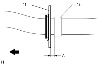
*1 Front Stabilizer Bar Protector *a Stopper (RH Side) Inside of the Vehicle Install the clip.
-
-
Install the front stabilizer bar bushing RH to the front stabilizer bar.
Tech Tips
Perform the same procedure as for the LH side.
-
-
INSTALL FRONT STABILIZER BAR
-
Install the front stabilizer bar with the 2 front stabilizer bar bushings to the vehicle body.
Note
-
Make sure that the identification mark is positioned as shown in the illustration.
-
Use wire or an equivalent tool to secure the front stabilizer bar.
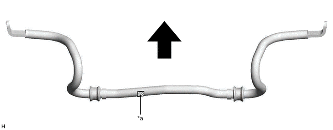
*a Identification Mark - - Front of the Vehicle - - -
-
-
INSTALL STEERING LINK ASSEMBLY
-
INSTALL FRONT STABILIZER BAR
-
INSTALL FRONT NO. 1 STABILIZER BRACKET LH
-
Install the front No. 2 stabilizer bracket LH to the front frame assembly.
-
Install the front No. 1 stabilizer bracket LH to the front frame assembly with the 2 bolts.
- Torque:
- 93 N*m { 948 kgf*cm, 69 ft.*lbf }
-
-
INSTALL FRONT NO. 1 STABILIZER BRACKET RH
Tech Tips
Perform the same procedure as for the LH side.
-
INSTALL EXHAUST MANIFOLD TO HEAD GASKET (for 2GR-FKS)
-
INSTALL EXHAUST MANIFOLD (TWC: Front Catalyst) (for 2GR-FKS)
-
INSTALL AIR FUEL RATIO SENSOR (for 2GR-FKS)
-
Engage the 3 wire harness clamps.
-
Connect the air fuel ratio sensor connector.
-
-
INSTALL FRONT NO. 3 EXHAUST PIPE SUB-ASSEMBLY (for 2GR-FKS)
-
CONNECT FRONT LOWER NO. 1 SUSPENSION ARM SUB-ASSEMBLY LH
-
CONNECT TIE ROD ASSEMBLY LH
-
CONNECT TIE ROD ASSEMBLY RH
Tech Tips
Perform the same procedure as for the LH side.
-
INSTALL FRONT STABILIZER LINK ASSEMBLY LH
-
Install the front stabilizer link assembly LH to the front shock absorber assembly and front stabilizer bar with the 2 nuts.
- Torque:
- 76 N*m { 775 kgf*cm, 56 ft.*lbf }
Tech Tips
If the ball joint turns together with the nut, use a 6 mm hexagon socket wrench to hold the stud bolt.
-
-
INSTALL FRONT STABILIZER LINK ASSEMBLY RH
Tech Tips
Perform the same procedure as for the LH side.
-
CONNECT STEERING INTERMEDIATE SHAFT ASSEMBLY
-
INSTALL FRONT FLOOR COVER LH (for 2GR-FKS)
-
INSPECT FOR EXHAUST GAS LEAK (for 2GR-FKS)
-
INSTALL NO. 2 ENGINE UNDER COVER
for 2GR-FKS: Click here
for 8AR-FTS: Click here
-
INSTALL FRONT WHEELS
-
INSPECT AND ADJUST FRONT WHEEL ALIGNMENT