AUDIO AND VISUAL SYSTEM(for 8 Inch Display), Diagnostic DTC:B15C3
| DTC Code | DTC Name |
|---|---|
| B15C3 | Speaker Output Short |
DESCRIPTION
This DTC is stored when a malfunction occurs in the speakers.
| DTC No. | Detection Item | DTC Detection Condition | Trouble Area |
|---|---|---|---|
| B15C3 | Speaker Output Short | A short is detected in the speaker output circuit. |
|
*: w/ Manual (SOS) Switch
WIRING DIAGRAM
Figure 1. for 9 Speakers
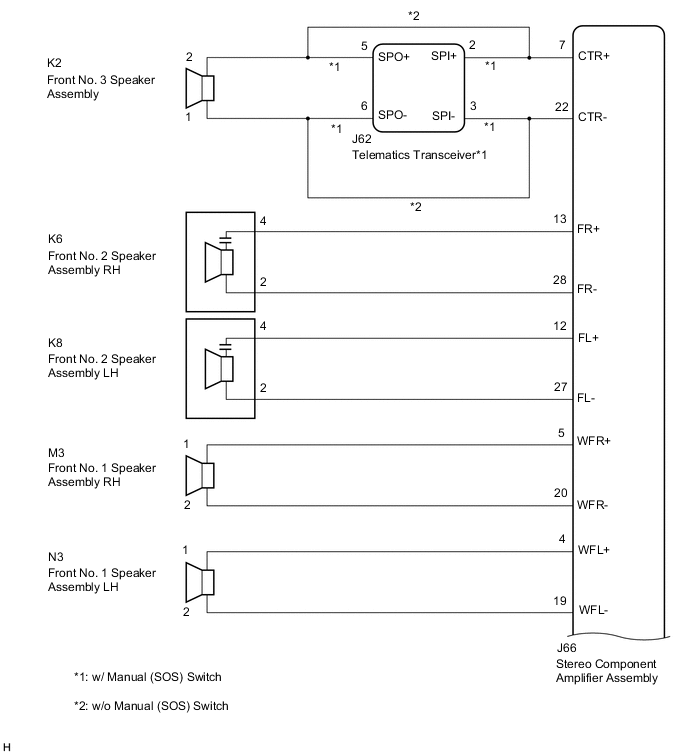
Figure 2. for 9 Speakers
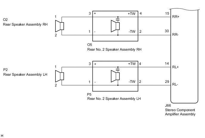
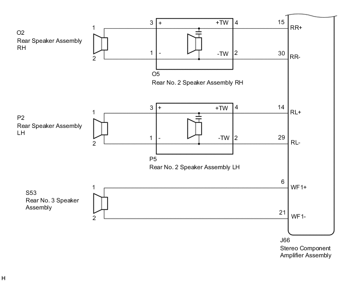
Figure 3. for 12 Speakers
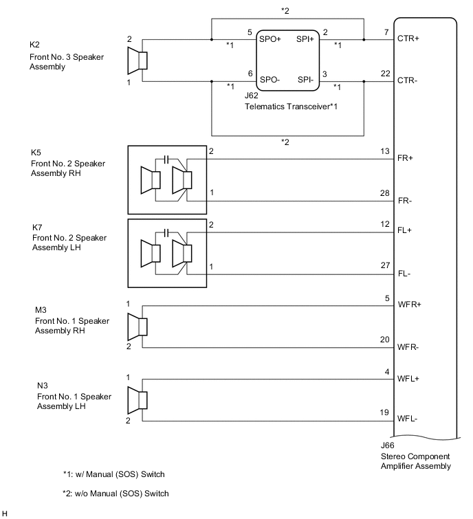
Figure 4. for 12 Speakers
CAUTION / NOTICE / HINT
Note
Depending on the parts that are replaced during vehicle inspection or maintenance, performing initialization, registration or calibration may be needed. Refer to Precaution for Audio and Visual System.
PROCEDURE
-
CHECK MODEL
-
Choose the model to be inspected.
Result Result Proceed to w/o Manual (SOS) Switch A w/ Manual (SOS) Switch B
B 
CHECK HARNESS AND CONNECTOR (STEREO COMPONENT AMPLIFIER ASSEMBLY, TELEMATICS TRANSCEIVER, SPEAKERS - BODY GROUND) Click here
A 
-
-
CHECK HARNESS AND CONNECTOR (STEREO COMPONENT AMPLIFIER ASSEMBLY, SPEAKERS - BODY GROUND)
-
Disconnect the J66 stereo component amplifier assembly connector.
-
Disconnect the K2 front No. 3 speaker assembly connector.
-
Disconnect the K6 and K8 front No. 2 speaker assembly connectors (for 9 Speakers).
-
Disconnect the K5 and K7 front No. 2 speaker assembly connectors (for 12 Speakers).
-
Disconnect the M3 and N3 front No. 1 speaker assembly connectors.
-
Disconnect the O5 and P5 rear No. 2 speaker assembly connectors.
-
Disconnect the S53 rear No. 3 speaker assembly connector (for 12 Speakers).
-
Measure the resistance according to the value(s) in the table below.
Standard Resistance Tester Connection Condition Specified Condition J66-7 (CTR+) or K2-2 - Body ground Always 10 kΩ or higher J66-22 (CTR-) or K2-1 - Body ground Always 10 kΩ or higher J66-13 (FR+) or K6-4 - Body ground*1 Always 10 kΩ or higher J66-13 (FR+) or K5-2 - Body ground*2 Always 10 kΩ or higher J66-28 (FR-) or K6-2 - Body ground*1 Always 10 kΩ or higher J66-28 (FR-) or K5-1 - Body ground*2 Always 10 kΩ or higher J66-12 (FL+) or K8-4 - Body ground*1 Always 10 kΩ or higher J66-12 (FL+) or K7-2 - Body ground*2 Always 10 kΩ or higher J66-27 (FL-) or K8-2 - Body ground*1 Always 10 kΩ or higher J66-27 (FL-) or K7-1 - Body ground*2 Always 10 kΩ or higher J66-5 (WFR+) or M3-1 - Body ground Always 10 kΩ or higher J66-20 (WFR-) or M3-2 - Body ground Always 10 kΩ or higher J66-4 (WFL+) or N3-1 - Body ground Always 10 kΩ or higher J66-19 (WFL-) or N3-2 - Body ground Always 10 kΩ or higher J66-15 (RR+) or O5-4 (+TW) - Body ground Always 10 kΩ or higher J66-30 (RR-) or O5-2 (-TW) - Body ground Always 10 kΩ or higher J66-14 (RL+) or P5-4 (+TW) - Body ground Always 10 kΩ or higher J66-29 (RL-) or P5-2 (-TW) - Body ground Always 10 kΩ or higher J66-6 (WF1+) or S53-1 - Body ground*2 Always 10 kΩ or higher J66-21 (WF1-) or S53-2 - Body ground*2 Always 10 kΩ or higher
-
*1: for 9 Speakers
-
*2: for 12 Speakers
Result Proceed to OK NG -
NG 
REPAIR OR REPLACE HARNESS OR CONNECTOR
OK
-
-
CHECK HARNESS AND CONNECTOR (REAR SPEAKER ASSEMBLY, REAR NO. 2 SPEAKER ASSEMBLY - BODY GROUND)
-
Disconnect the O2 and P2 rear speaker assembly connectors.
-
Disconnect the O5 and P5 rear No. 2 speaker assembly connectors.
-
Measure the resistance according to the value(s) in the table below.
Standard Resistance Tester Connection Condition Specified Condition O2-1 or O5-3 (+) - Body ground Always 10 kΩ or higher O2-2 or O5-1 (-) - Body ground Always 10 kΩ or higher P2-1 or P5-3 (+) - Body ground Always 10 kΩ or higher P2-2 or P5-1 (-) - Body ground Always 10 kΩ or higher Result Proceed to OK NG
NG
REPAIR OR REPLACE HARNESS OR CONNECTOR
OK
-
-
INSPECT FRONT NO. 3 SPEAKER ASSEMBLY
-
Remove the front No. 3 speaker assembly.
-
Inspect the front No. 3 speaker assembly.
Result Proceed to OK NG
NG
REPLACE FRONT NO. 3 SPEAKER ASSEMBLY Click here
OK
-
-
INSPECT FRONT NO. 2 SPEAKER ASSEMBLY
-
Remove the front No. 2 speaker assembly.
-
Inspect the front No. 2 speaker assembly.
-
Clear the DTCs.
Body Electrical > Navigation System > Clear DTCs -
Recheck for DTCs and check that no DTCs are output.
Body Electrical > Navigation System > Trouble CodesOK No DTCs are output. Result Proceed to OK NG
OK
END
NG
-
-
INSPECT FRONT NO. 1 SPEAKER ASSEMBLY
-
Remove the front No. 1 speaker assembly.
-
Inspect the front No. 1 speaker assembly.
Result Proceed to OK NG
NG
REPLACE FRONT NO. 1 SPEAKER ASSEMBLY Click here
OK
-
-
INSPECT REAR SPEAKER ASSEMBLY
-
Remove the rear speaker assembly.
-
Inspect the rear speaker assembly.
Result Result Proceed to OK (for 9 Speakers) A OK (for 12 Speakers) B NG C
B
INSPECT REAR NO. 2 SPEAKER ASSEMBLY Click here
C
REPLACE REAR SPEAKER ASSEMBLY Click here
A
-
-
INSPECT REAR NO. 2 SPEAKER ASSEMBLY
-
Remove the rear No. 2 speaker assembly.
-
Inspect the rear No. 2 speaker assembly.
-
Clear the DTCs.
Body Electrical > Navigation System > Clear DTCs -
Recheck for DTCs and check that no DTCs are output.
Body Electrical > Navigation System > Trouble CodesOK No DTCs are output. Result Proceed to OK NG
OK
END
NG
REPLACE STEREO COMPONENT AMPLIFIER ASSEMBLY Click here
-
-
INSPECT REAR NO. 2 SPEAKER ASSEMBLY
-
Remove the rear No. 2 speaker assembly.
-
Inspect the rear No. 2 speaker assembly.
-
Clear the DTCs.
Body Electrical > Navigation System > Clear DTCs -
Recheck for DTCs and check that no DTCs are output.
Body Electrical > Navigation System > Trouble CodesOK No DTCs are output. Result Proceed to OK NG
OK
END
NG
-
-
INSPECT REAR NO. 3 SPEAKER ASSEMBLY
-
Remove the rear No. 3 speaker assembly.
-
Inspect the rear No. 3 speaker assembly.
Result Proceed to OK NG
OK
REPLACE STEREO COMPONENT AMPLIFIER ASSEMBLY Click here
NG
REPLACE REAR NO. 3 SPEAKER ASSEMBLY Click here
-
-
CHECK HARNESS AND CONNECTOR (STEREO COMPONENT AMPLIFIER ASSEMBLY, TELEMATICS TRANSCEIVER, SPEAKERS - BODY GROUND)
-
Disconnect the J66 stereo component amplifier assembly connector.
-
Disconnect the J62 telematics transceiver connector.
-
Disconnect the K6 and K8 front No. 2 speaker assembly connectors (for 9 Speakers).
-
Disconnect the K5 and K7 front No. 2 speaker assembly connectors (for 12 Speakers).
-
Disconnect the M3 and N3 front No. 1 speaker assembly connectors.
-
Disconnect the O5 and P5 rear No. 2 speaker assembly connectors.
-
Disconnect the S53 rear No. 3 speaker assembly connector (for 12 Speakers).
-
Measure the resistance according to the value(s) in the table below.
Standard Resistance Tester Connection Condition Specified Condition J66-7 (CTR+) or J62-2 (SPI+) - Body ground Always 10 kΩ or higher J66-22 (CTR-) or J62-3 (SPI-) - Body ground Always 10 kΩ or higher J66-13 (FR+) or K6-4 - Body ground*1 Always 10 kΩ or higher J66-13 (FR+) or K5-2 - Body ground*2 Always 10 kΩ or higher J66-28 (FR-) or K6-2 - Body ground*1 Always 10 kΩ or higher J66-28 (FR-) or K5-1 - Body ground*2 Always 10 kΩ or higher J66-12 (FL+) or K8-4 - Body ground*1 Always 10 kΩ or higher J66-12 (FL+) or K7-2 - Body ground*2 Always 10 kΩ or higher J66-27 (FL-) or K8-2 - Body ground*1 Always 10 kΩ or higher J66-27 (FL-) or K7-1 - Body ground*2 Always 10 kΩ or higher J66-5 (WFR+) or M3-1 - Body ground Always 10 kΩ or higher J66-20 (WFR-) or M3-2 - Body ground Always 10 kΩ or higher J66-4 (WFL+) or N3-1 - Body ground Always 10 kΩ or higher J66-19 (WFL-) or N3-2 - Body ground Always 10 kΩ or higher J66-15 (RR+) or O5-4 (+TW) - Body ground Always 10 kΩ or higher J66-30 (RR-) or O5-2 (-TW) - Body ground Always 10 kΩ or higher J66-14 (RL+) or P5-4 (+TW) - Body ground Always 10 kΩ or higher J66-29 (RL-) or P5-2 (-TW) - Body ground Always 10 kΩ or higher J66-6 (WF1+) or S53-1 - Body ground*2 Always 10 kΩ or higher J66-21 (WF1-) or S53-2 - Body ground*2 Always 10 kΩ or higher
-
*1: for 9 Speakers
*2: for 12 Speakers
Result Proceed to OK NG -
NG
REPAIR OR REPLACE HARNESS OR CONNECTOR
OK
-
-
CHECK HARNESS AND CONNECTOR (FRONT NO. 3 SPEAKER ASSEMBLY, TELEMATICS TRANSCEIVER - BODY GROUND)
-
Disconnect the K2 front No. 3 speaker assembly connector.
-
Disconnect the J62 telematics transceiver connector.
-
Measure the resistance according to the value(s) in the table below.
Standard Resistance Tester Connection Condition Specified Condition K2-2 or J62-5 (SPO+) - Body ground Always 10 kΩ or higher K2-1 or J62-6 (SPO-) - Body ground Always 10 kΩ or higher Result Proceed to OK NG
NG
REPAIR OR REPLACE HARNESS OR CONNECTOR
OK
-
-
CHECK HARNESS AND CONNECTOR (REAR SPEAKER ASSEMBLY, REAR NO. 2 SPEAKER ASSEMBLY - BODY GROUND)
-
Disconnect the O2 and P2 rear speaker assembly connectors.
-
Disconnect the O5 and P5 rear No. 2 speaker assembly connectors.
-
Measure the resistance according to the value(s) in the table below.
Standard Resistance Tester Connection Condition Specified Condition O2-1 or O5-3 (+) - Body ground Always 10 kΩ or higher O2-2 or O5-1 (-) - Body ground Always 10 kΩ or higher P2-1 or P5-3 (+) - Body ground Always 10 kΩ or higher P2-2 or P5-1 (-) - Body ground Always 10 kΩ or higher Result Proceed to OK NG
NG
REPAIR OR REPLACE HARNESS OR CONNECTOR
OK
-
-
INSPECT FRONT NO. 3 SPEAKER ASSEMBLY
-
Remove the front No. 3 speaker assembly.
-
Inspect the front No. 3 speaker assembly.
Result Proceed to OK NG
NG
REPLACE FRONT NO. 3 SPEAKER ASSEMBLY Click here
OK
-
-
INSPECT FRONT NO. 2 SPEAKER ASSEMBLY
-
Remove the front No. 2 speaker assembly.
-
Inspect the front No. 2 speaker assembly.
-
Clear the DTCs.
Body Electrical > Navigation System > Clear DTCs -
Recheck for DTCs and check that no DTCs are output.
Body Electrical > Navigation System > Trouble CodesOK No DTCs are output. Result Proceed to OK NG
OK
END
NG
-
-
INSPECT FRONT NO. 1 SPEAKER ASSEMBLY
-
Remove the front No. 1 speaker assembly.
-
Inspect the front No. 1 speaker assembly.
Result Proceed to OK NG
NG
REPLACE FRONT NO. 1 SPEAKER ASSEMBLY Click here
OK
-
-
INSPECT REAR SPEAKER ASSEMBLY
-
Remove the rear speaker assembly.
-
Inspect the rear speaker assembly.
Result Result Proceed to OK (for 9 Speakers) A OK (for 12 Speakers) B NG C
B
INSPECT REAR NO. 2 SPEAKER ASSEMBLY Click here
C
REPLACE REAR SPEAKER ASSEMBLY Click here
A
-
-
INSPECT REAR NO. 2 SPEAKER ASSEMBLY
-
Remove the rear No. 2 speaker assembly.
-
Inspect the rear No. 2 speaker assembly.
-
Clear the DTCs.
Body Electrical > Navigation System > Clear DTCs -
Recheck for DTCs and check that no DTCs are output.
Body Electrical > Navigation System > Trouble CodesOK No DTCs are output. Result Proceed to OK NG
OK
GO TO STEP 21 Click here
NG
REPLACE STEREO COMPONENT AMPLIFIER ASSEMBLY Click here
-
-
INSPECT REAR NO. 2 SPEAKER ASSEMBLY
-
Remove the rear No. 2 speaker assembly.
-
Inspect the rear No. 2 speaker assembly.
-
Clear the DTCs.
Body Electrical > Navigation System > Clear DTCs -
Recheck for DTCs and check that no DTCs are output.
Body Electrical > Navigation System > Trouble CodesOK No DTCs are output. Result Proceed to OK NG
OK
END
NG
-
-
INSPECT REAR NO. 3 SPEAKER ASSEMBLY
-
Remove the rear No. 3 speaker assembly.
-
Inspect the rear No. 3 speaker assembly.
Result Proceed to OK NG
NG
REPLACE REAR NO. 3 SPEAKER ASSEMBLY Click here
OK
-
-
INSPECT TELEMATICS TRANSCEIVER
-
Remove the telematics transceiver.
-
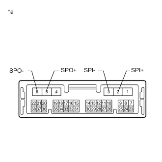
*a Component without harness connected
(Telematics Transceiver)
Measure the resistance according to the value(s) in the table below.
Standard Resistance Tester Connection Condition Specified Condition 2 (SPI+) - 5 (SPO+) Always Below 1 Ω 3 (SPI-) - 6 (SPO-) Always Below 1 Ω 2 (SPI+) - 3 (SPI-) Always 10 kΩ or higher 5 (SPO+) - 6 (SPO-) Always 10 kΩ or higher 2 (SPI+) - Body ground Always 10 kΩ or higher 3 (SPI-) - Body ground Always 10 kΩ or higher Result Proceed to OK NG
OK
REPLACE STEREO COMPONENT AMPLIFIER ASSEMBLY Click here
NG
REPLACE TELEMATICS TRANSCEIVER Click here
-