ЗАДНИЙ САЛЬНИК КОЛЕНЧАТОГО ВАЛА УСТАНОВКА

PROCEDURE
-
INSTALL REAR ENGINE OIL SEAL
-
Using height adjustment attachments and plate lift attachments, place the engine assembly on a flat level surface.
Note
-
Using height adjustment attachments and plate lift attachments, keep the engine assembly horizontal.
-
To prevent the oil pan sub-assembly from deforming, do not place any attachments under the oil pan sub-assembly of the engine assembly.
-
Using an engine sling device and engine lift, secure the engine assembly before servicing.
-
-
Apply MP grease to the lip of a new rear engine oil seal.
Note
-
Keep the lip free from foreign matter.
-
Do not allow MP grease to contact the dust seal.
-
-
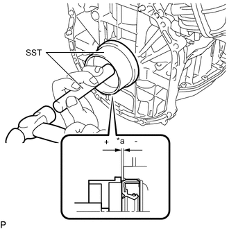
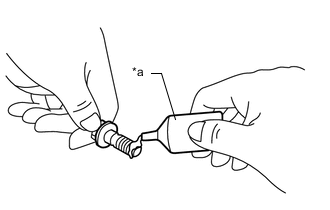
*a -0.2 to 0.9 mm (-0.00787 to 0.0354 in.) Using SST and a hammer, tap in the rear engine oil seal.
- SST
- 09223-15030
- 09950-70010 ( 09951-07150 )
Standard Depth -0.2 to 0.9 mm (-0.00787 to 0.0354 in.) (From the edge of the cylinder block sub-assembly and stiffening crankcase assembly) Note
Do not tap in the rear engine oil seal at an angle.
-
-
INSTALL DRIVE PLATE AND RING GEAR SUB-ASSEMBLY
-
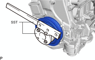
Using SST, hold the crankshaft.
- SST
- 09213-54015
- 91551-80650
Tech Tips
Part number of installation bolt for SST (crankshaft pulley holding tool): 91551-80650 (quantity: 2)
-
Clean the 8 bolts and bolt holes.
-
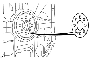
Install the front drive plate spacer.
Tech Tips
Align the pin of the front drive plate spacer with the pin hole of the crankshaft.
-
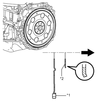
*1 Drive Plate and Ring Gear Sub-assembly *2 Rear Drive Plate Spacer 
Transaxle Side Install the drive plate and ring gear sub-assembly and rear drive plate spacer to the crankshaft.
Note
As the rear drive plate spacer and drive plate and ring gear sub-assembly are not reversible, be sure to install them so that they are facing in the direction shown in the illustration.
-
*a Adhesive Apply adhesive to 2 or 3 threads at the end of each of the 8 bolts.
Adhesive Toyota Genuine Adhesive 1324, Three Bond 1324 or equivalent -
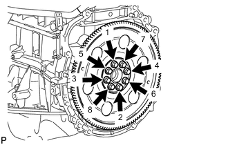
Install and uniformly tighten the 8 bolts in several steps in the sequence shown in the illustration.
- Torque:
- 98 N*m { 999 kgf*cm, 72 ft.*lbf }
Note
Do not start the engine for at least 1 hour after installing the drive plate and ring gear sub-assembly.
-
-
INSTALL CONTINUOUSLY VARIABLE TRANSAXLE ASSEMBLY