SFI SYSTEM, Diagnostic DTC:P0133
| DTC Code | DTC Name |
|---|---|
| P0133 | Oxygen Sensor Circuit Slow Response (Bank 1 Sensor 1) |
DESCRIPTION
Refer to DTC P2195 Click here.
Tech Tips
Sensor 1 refers to the sensor mounted in front of the three-way catalytic converter and located near the engine assembly.
| DTC No. | DTC Detection Condition | Trouble Area |
|---|---|---|
| P0133 | The calculated value for the air fuel ratio sensor response rate deterioration level is less than the threshold. (2 trip detection logic) |
|
MONITOR DESCRIPTION
After the engine is warmed up, the ECM performs air fuel ratio feedback control to maintain the air fuel ratio at the stoichiometric level.
If the value for the air fuel ratio sensor response rate deterioration level is less than the threshold, the ECM interprets this as a malfunction and stores the DTC.
CONFIRMATION DRIVING PATTERN
-
Connect the GTS to the DLC3.
-
Turn the ignition switch to ON and turn the GTS on.
-
Clear DTCs (even if no DTCs are stored, perform the clear DTC operation) Click here.
-
Turn the ignition switch off and wait for at least 30 seconds.
-
Turn the ignition switch to ON and turn the GTS on.
-
Start the engine and warm it up until the engine coolant temperature reaches 75°C (167°F) or higher.
Tech Tips
Check the engine coolant temperature is 20°C (68°F) or less at engine started.
-
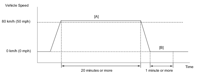
Perform the following the confirmation driving pattern.
CAUTION:
When performing the confirmation driving pattern, obey all speed limits and traffic laws.
-
Drive the vehicle at 80 km/h (50 mph) or more for 20 minutes or more [A].
-
Stop the vehicle.
-
Idle the engine for 1 minute or more [B].
-
Enter the following menus: Powertrain / Engine / Trouble Codes.
-
Read pending DTCs.
Tech Tips
-
If a pending DTC is output, the system is malfunctioning.
-
If a pending DTC is not output, perform the following procedure.
-
-
Enter the following menus: Powertrain / Engine / Utility / All Readiness.
-
Input the DTC: P0133.
-
Check the DTC judgment result.
GTS Display Description NORMAL
-
DTC judgment completed
-
System normal
ABNORMAL
-
DTC judgment completed
-
System abnormal
INCOMPLETE
-
DTC judgment not completed
-
Perform driving pattern after confirming DTC enabling conditions
N/A
-
Unable to perform DTC judgment
-
Number of DTCs which do not fulfill DTC preconditions has reached ECU memory limit
Tech Tips
-
If the judgment result shows NORMAL, the system is normal.
-
If the judgment result shows ABNORMAL, the system has a malfunction.
-
-
If the test result is INCOMPLETE or N/A and no DTC is output, perform a universal trip and check for permanent DTCs Click here.
Tech Tips
-
If a permanent DTC is output, the system is malfunctioning.
-
If no permanent DTC is output, the system is normal.
-
WIRING DIAGRAM
Refer to DTC P0030 Click here.
CAUTION / NOTICE / HINT
Note
Inspect the fuses for circuits related to this system before performing the following inspection procedure.
Tech Tips
-
Read freeze frame data using the GTS. The ECM records vehicle and driving condition information as freeze frame data the moment a DTC is stored. When troubleshooting, freeze frame data can help determine if the vehicle was moving or stationary, if the engine was warmed up or not, if the air fuel ratio was lean or rich, and other data from the time the malfunction occurred.
-
Sensor 1 refers to the sensor closest to the engine assembly.
-
Sensor 2 refers to the sensor farthest away from the engine assembly.
PROCEDURE
-
CHECK ANY OTHER DTCS OUTPUT (IN ADDITION TO DTC P0133)
-
Connect the GTS to the DLC3.
-
Turn the ignition switch to ON.
-
Turn the GTS on.
-
Enter the following menus: Powertrain / Engine / Trouble Codes.
-
Read DTCs.
Result Result Proceed to DTC P0133 is output A DTC P0133 and other DTCs are output B Tech Tips
If any DTCs other than P0133 are output, troubleshoot those DTCs first.
B 
GO TO DTC CHART Click here
A 
-
-
PERFORM ACTIVE TEST USING GTS (CONTROL THE INJECTION VOLUME)
-
Connect the GTS to the DLC3.
-
Start the engine.
-
Turn the GTS on.
-
Warm up the engine and run the engine at an engine speed of 2500 rpm for approximately 90 seconds.
-
Enter the following menus: Powertrain / Engine / Active Test / Control the Injection Volume.
-
Perform the Control the Injection Volume operation with the engine idling.
-
Monitor the output voltages of the air fuel ratio and heated oxygen sensors (AFS Voltage B1S1 and O2S B1S2) displayed on the GTS.
Tech Tips
-
Change the fuel injection volume within the range of -12.5% to +12.5%. The injection volume can be changed in fine gradations.
-
The air fuel ratio sensor has an output delay of a few seconds and the heated oxygen sensor has a maximum output delay of approximately 20 seconds.
-
If the sensor output voltage does not change (almost no reaction) while performing the Active Test, the sensor may be malfunctioning.
GTS Display (Sensor) Injection Volume Status Voltage AFS Voltage B1S1
(Air fuel ratio)
+12.5% Rich Below 2.0 V AFS Voltage B1S1
(Air fuel ratio)
-12.5% Lean Higher than 2.4 V O2S B1S2
(Heated oxygen)
+12.5% Rich Higher than 0.55 V O2S B1S2
(Heated oxygen)
-12.5% Lean Below 0.4 V Result Status of AFS Voltage B1S1 Status of O2S B1S2 Air Fuel Ratio Condition and Air Fuel Ratio Sensor Condition Proceed to Lean/Rich Lean/Rich Normal A Lean Lean Actual air fuel ratio lean B Rich Rich Actual air fuel ratio rich B Lean Lean/Rich Air fuel ratio sensor malfunction C Rich Lean/Rich Air fuel ratio sensor malfunction C
-
Lean: During the Control the Injection Volume Active Test, the air fuel ratio sensor output voltage (AFS Voltage) is consistently higher than 2.4 V, and the heated oxygen sensor output voltage (O2S) is consistently below 0.4 V.
-
Rich: During the Control the Injection Volume Active Test, the AFS Voltage is consistently below 2.0 V, and the O2S is consistently higher than 0.55 V.
-
Lean/Rich: During the Control the Injection Volume Active Test, the output voltage of the heated oxygen sensor alternates correctly.
Tech Tips
Refer to "Data List / Active Test" [AFS Voltage B1S1 and O2S B1S2] Click here.
-
B 
INSPECT AIR FUEL RATIO SENSOR (HEATER RESISTANCE) Click here
C
REPLACE AIR FUEL RATIO SENSOR Click here
A
-
-
CHECK WHETHER DTC OUTPUT RECURS (DTC P0133)
-
Connect the GTS to the DLC3.
-
Turn the ignition switch to ON.
-
Turn the GTS on.
-
Clear the DTCs Click here.
-
Turn the ignition switch off and wait for at least 30 seconds.
-
Turn the ignition switch to ON.
-
Turn the GTS on.
-
Start the engine and warm it up.
-
Drive the vehicle in accordance with the driving pattern described in Confirmation Driving Pattern.
-
Enter the following menus: Powertrain / Engine / Utility / All Readiness.
-
Input the DTC: P0133.
-
Check the DTC judgment result.
Result Result Proceed to NORMAL (DTC is not output) A ABNORMAL (DTC P0133 is output) B
A
CHECK FOR INTERMITTENT PROBLEMS Click here
B
REPLACE AIR FUEL RATIO SENSOR Click here
-
-
INSPECT AIR FUEL RATIO SENSOR (HEATER RESISTANCE)
-
Inspect the air fuel ratio sensor Click here.
NG
REPLACE AIR FUEL RATIO SENSOR Click here
OK
-
-
CHECK INTAKE SYSTEM
-
Check the intake system Click here.
NG
REPAIR OR REPLACE INTAKE SYSTEM
OK
-
-
CHECK FUEL PRESSURE (LOW PRESSURE SIDE)
-
Check the fuel pressure (low pressure side) Click here.
NG
INSPECT FUEL PUMP ASSEMBLY Click here
OK
-
-
INSPECT FUEL INJECTOR ASSEMBLY (FOR PORT INJECTION)
-
Inspect the fuel injector assembly (for port injection) Click here.
NG
REPLACE FUEL INJECTOR ASSEMBLY (FOR PORT INJECTION) Click here
OK
-
-
READ VALUE USING GTS (FUEL PRESS)
-
Connect the GTS to the DLC3.
-
Turn the ignition switch to ON.
-
Turn the GTS on.
-
Start the engine.
-
Enter the following menus: Powertrain / Engine / Data List / Fuel Press.
-
Read the value displayed on the GTS.
Standard GTS display Condition Specified condition Fuel Press Idling 3000 to 5000 kPa (30.6 to 50.9 kgf/cm2, 436 to 725 psi)
NG
REPAIR OR REPLACE FUEL LINE (HIGH PRESSURE SIDE)
OK
-
-
INSPECT FUEL INJECTOR ASSEMBLY (FOR DIRECT INJECTION)
-
Inspect the fuel injector assembly (for direct injection) Click here.
NG
REPLACE FUEL INJECTOR ASSEMBLY (FOR DIRECT INJECTION) Click here
OK
-
-
REPLACE AIR FUEL RATIO SENSOR
-
Replace the air fuel ratio sensor Click here.
NEXT
-
-
CHECK WHETHER DTC OUTPUT RECURS (DTC P0133)
-
Connect the GTS to the DLC3.
-
Turn the ignition switch to ON.
-
Turn the GTS on.
-
Clear the DTCs Click here.
-
Turn the ignition switch off and wait for at least 30 seconds.
-
Turn the ignition switch to ON.
-
Turn the GTS on.
-
Start the engine and warm it up.
-
Drive the vehicle in accordance with the driving pattern described in Confirmation Driving Pattern.
-
Enter the following menus: Powertrain / Engine / Utility / All Readiness.
-
Input the DTC: P0133.
-
Check the DTC judgment result.
Result Result Proceed to ABNORMAL (DTC P0133 is output) A NORMAL (DTC is not output) B
B
END
A
-
-
REPLACE ECM
-
Replace the ECM Click here.
NEXT
-
-
CHECK WHETHER DTC OUTPUT RECURS (DTC P0133)
-
Connect the GTS to the DLC3.
-
Turn the ignition switch to ON.
-
Turn the GTS on.
-
Clear the DTCs Click here.
-
Turn the ignition switch off and wait for at least 30 seconds.
-
Turn the ignition switch to ON.
-
Turn the GTS on.
-
Start the engine and warm it up.
-
Drive the vehicle in accordance with the driving pattern described in Confirmation Driving Pattern.
-
Enter the following menus: Powertrain / Engine / Utility / All Readiness.
-
Input the DTC: P0133.
-
Check that the DTC judgment result is NORMAL.
NEXT
END
-
-
INSPECT FUEL PUMP ASSEMBLY
-
Inspect the fuel pump assembly Click here.
OK
REPAIR OR REPLACE FUEL LINE (LOW PRESSURE SIDE)
NG
REPLACE FUEL PUMP ASSEMBLY Click here
-