CONTINUOUSLY VARIABLE TRANSAXLE SYSTEM Pattern Select Switch Sport Mode Circuit
| DTC Code | DTC Name |
|---|---|
| Pattern Select Switch Sport Mode Circuit |
DESCRIPTION
The ECM memory contains programs for normal and sport shift patterns.
By following the programs corresponding to the signals from the combination switch assembly, the park/neutral position switch and other various sensors, the ECM switches the shift control solenoid valves on and off, and controls the transaxle gear ratio.
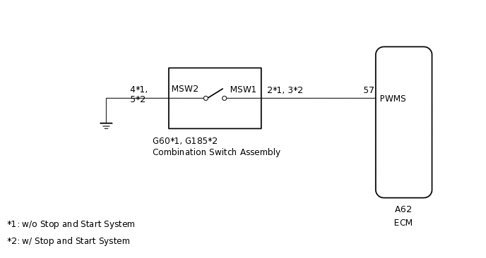
WIRING DIAGRAM
CAUTION / NOTICE / HINT
Perform initialization when parts related to the continuously variable transaxle are replaced.
Check that no DTCs are stored after performing initialization.
PROCEDURE
INSPECT COMBINATION SWITCH ASSEMBLY
-
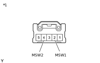
*1
Combination Switch Assembly
w/o Stop and Start System:
Remove the combination switch assembly.
Measure the resistance according to the value(s) in the table below.
Standard Resistance
Tester Connection
Switch Condition
Specified Condition
2 (MSW1) - 4 (MSW2)
Combination switch assembly (SPORT) on
Below 1 Ω
2 (MSW1) - 4 (MSW2)
Combination switch assembly (SPORT) off
10 kΩ or higher
-
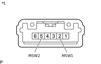
*1
Combination Switch Assembly
w/ Stop and Start System:
Remove the combination switch assembly.
Measure the resistance according to the value(s) in the table below.
Standard Resistance
Tester Connection
Switch Condition
Specified Condition
2 (MSW1) - 5 (MSW2)
Combination switch assembly (SPORT) on
Below 1 Ω
2 (MSW1) - 5 (MSW2)
Combination switch assembly (SPORT) off
10 kΩ or higher
Result
Proceed to
OK
NG
-
CHECK HARNESS AND CONNECTOR (COMBINATION SWITCH ASSEMBLY - BODY GROUND)
-
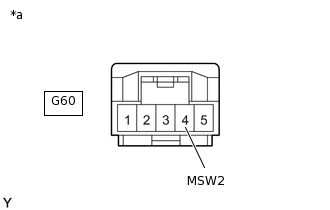
*a
Front view of wire harness connector
(to Combination Switch Assembly)
w/o Stop and Start System:
Disconnect the combination switch assembly connector.
Measure the resistance according to the value(s) in the table below.
Standard Resistance
Tester Connection
Condition
Specified Condition
G60-4 (MSW2) - Body ground
Always
Below 1 Ω
-
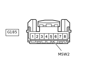
*a
Front view of wire harness connector
(to Combination Switch Assembly)
w/ Stop and Start System:
Disconnect the combination switch assembly connector.
Measure the resistance according to the value(s) in the table below.
Standard Resistance
Tester Connection
Condition
Specified Condition
G185-5 (MSW2) - Body ground
Always
Below 1 Ω
Result
Proceed to
OK
NG
NG REPAIR OR REPLACE HARNESS OR CONNECTOR
-
CHECK HARNESS AND CONNECTOR (COMBINATION SWITCH ASSEMBLY - ECM)
-
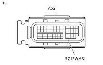
*a
Front view of wire harness connector
(to ECM)
Disconnect the ECM connector.
Measure the resistance according to the value(s) in the table below.
Standard Resistance
Tester Connection
Switch Condition
Specified Condition
A62-57 (PWMS) - Body ground
Combination switch assembly (SPORT) on
Below 1 Ω
A62-57 (PWMS) - Body ground
Combination switch assembly (SPORT) off
10 kΩ or higher
Result
Proceed to
OK
NG
NG REPAIR OR REPLACE HARNESS OR CONNECTOR
-
REPLACE ECM
Replace the ECM.
for 3ZR-FAE:
for 3ZR-FE:
Result
Proceed to
NEXT