SFI SYSTEM
-
CONSTRUCTION
-
The basic construction of the air fuel ratio sensor (sensor 1) and the air fuel ratio sensor (sensor 2)* is the same. However, they are divided into the cup type and the planar type, in accordance with the different types of heater construction that are used.
-
The air fuel ratio sensor (sensor 1) is located upstream of the three-way catalyst in the converter assembly.
-
The air fuel ratio sensor (sensor 2) is located downstream of the three-way catalyst in the converter assembly.*
-
The planar type air fuel ratio sensor (sensor 1) uses alumina, which excels in heat conductivity and insulation, to integrate a sensor element with the heater, thus achieving the excellent warm-up performance of the sensor.
-
The cup type air fuel ratio sensor (sensor 2) contains a sensor element that surrounds the heater.*
-
*: Models with gasoline particulate filter (GPF) system
Figure 1. Air Fuel Ratio Sensor (Sensor 1) (Planar Type)
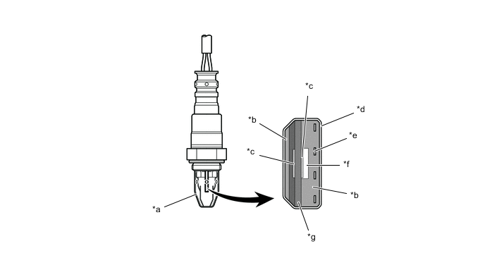
*a Cover *b Alumina *c Platinum Electrode *d Coating (Ceramic) *e Heater *f Atmosphere *g Sensor Element (Zirconia) - - Figure 2. Air Fuel Ratio Sensor (Sensor 2) (Cup Type)
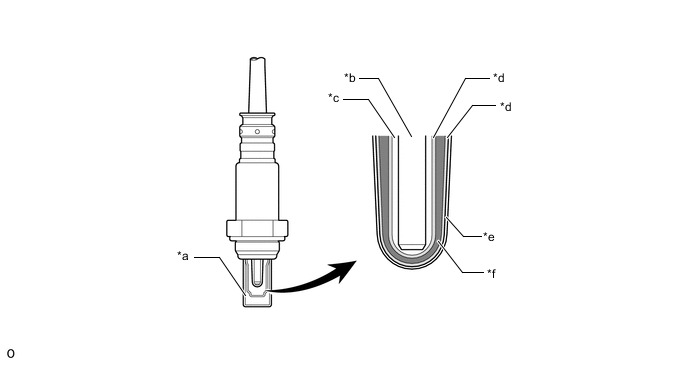
*a Cover *b Heater *c Atmosphere *d Platinum Electrode *e Coating (Ceramic) *f Sensor Element (Zirconia) Figure 3. Output Characteristics of The Air Fuel Ratio Sensor (Sensor 1)
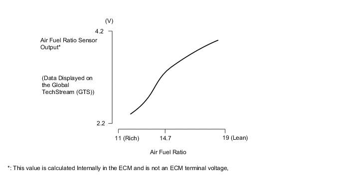
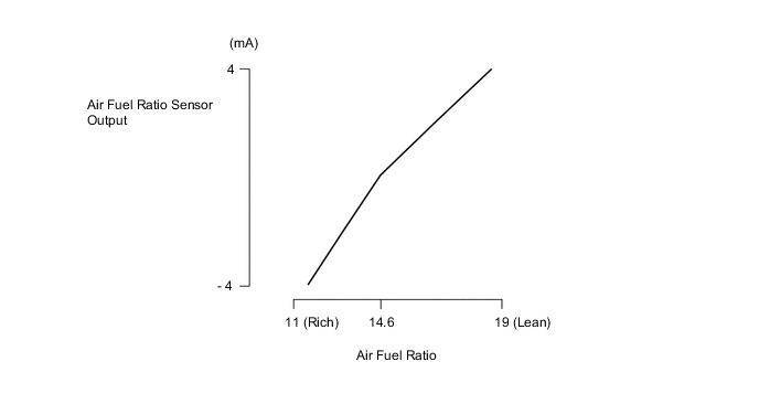
Figure 4. Output Characteristics of The Air Fuel Ratio Sensor (Sensor 2)
-
-