CANVAS TOP ROOF HOUSING INSTALLATION
PROCEDURE
CLEAN SLIDING ROOF HOUSING SUB-ASSEMBLY
When reusing the sliding roof housing sub-assembly:
-
Using a scraper, remove any remaining adhesive dam and adhesive residue from the sliding roof housing sub-assembly.
Note:Be careful not to damage the sliding roof housing sub-assembly.
-
Clean the outer circumference of the sliding roof housing sub-assembly with a non-residue solvent.
Note:Do not touch the sliding roof housing sub-assembly surface after cleaning it.
Even if using a new sliding roof housing sub-assembly, clean the sliding roof housing sub-assembly with a non-residue solvent.
CLEAN VEHICLE BODY
-
*a
Vehicle Body

Adhesive
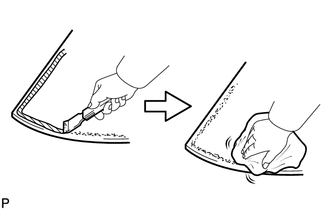
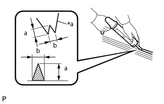
Clean and shape the contact surfaces of the vehicle body.
Using a knife, cut away excess adhesive on the contact surfaces of the vehicle body as shown in the illustration.
Note:Be careful not to damage the vehicle body.
Tip:Leave as much adhesive on the vehicle body as possible.
Clean the contact surfaces of the vehicle body with a piece of cloth saturated with non-residue solvent.
Tip:Even if all the adhesive has been removed, clean the vehicle body.
-
INSTALL SLIDING ROOF HOUSING SUB-ASSEMBLY
Using a brush, coat the installation surface on the vehicle body with Primer M.
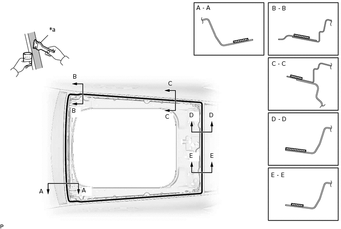
*a
Brush
-
-
Primer M
-
-
Note:Do not coat the adhesive with Primer M.
Do not apply too much primer M.
Allow the primer M to dry for 3 minutes or more.
Throw away any leftover primer M.
Tip:If an area other than specified is coated by accident, wipe off the primer M with a clean piece of cloth before it dries.
Using a brush or sponge, coat the application area of the adhesive with primer M.
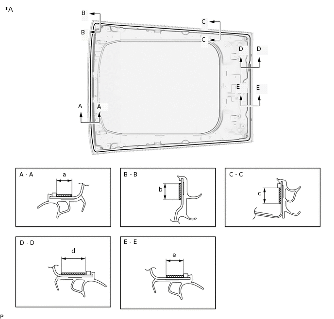
*A
Back Side
-
-
Primer M
-
-
Standard Dimension
Area
Dimension
Area
Dimension
a
12.0 mm (0.472 in.) or more.
b
12.0 mm (0.472 in.) or more.
c
12.0 mm (0.472 in.) or more.
d
19.0 mm (0.748 in.) or more.
e
12.0 mm (0.472 in.) or more.
-
-
Note:Do not apply too much primer M.
Allow the primer M to dry for 3 minutes or more.
Throw away any leftover primer M.
Tip:If an area other than specified is coated by accident, wipe off the primer M with a clean piece of cloth before it dries.
Apply adhesive to the sliding roof housing sub-assembly.
Adhesive
Toyota Genuine Windshield Glass Adhesive or equivalent
-
*a
Nozzle
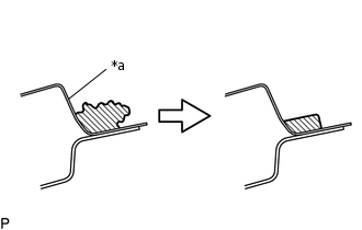
Cut off the tip of the cartridge nozzle as shown in the illustration.
Standard Dimension
Area
Dimension
a
10.0 mm (0.394 in.) or more
b
8.0 mm (0.315 in.) or more
Load the sealer gun with the cartridge.
Apply adhesive to the sliding roof housing sub-assembly as shown in the illustration.
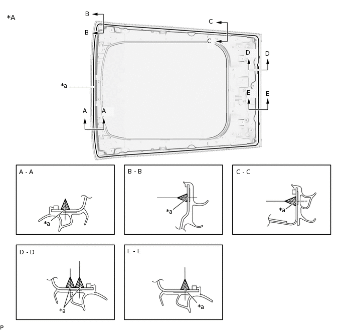
*A
Back Side
-
-
*a
Adhesive positioning center line
-
-
Adhesive
-
-
Using a scraper, remove any excess or protruding adhesive.
Hold the sliding roof housing sub-assembly using protective tape until the applied adhesive becomes hard.
Note:Do not drive the vehicle for the time described in the table below.
Minimum Time
Temperature
Minimum Time prior to Driving Vehicle
35°C (95°F)
1 hour and 30 minutes
20°C (68°F)
5 hours
5°C (41°F)
24 hours
-
-
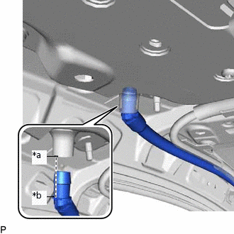
*a
Sliding Roof Housing Sub-assembly Rib
*b
Sliding Roof Drain Hose Rib
Align the sliding roof housing sub-assembly rib with the sliding roof drain hose rib as shown in the illustration and connect the sliding roof drain hose.
Note:Check that the sliding roof drain hose is securely attached to the sliding roof housing sub-assembly.
Tip:Use the same procedure for the other 3 sliding roof drain hoses.
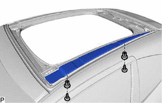
INSTALL SLIDING ROOF SEAL
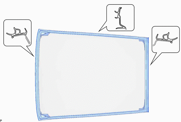
Apply new butyl tape to the sliding roof seal as shown in the illustration.
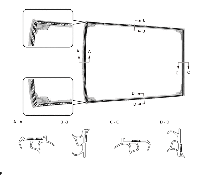
Butyl Tape
-
-
Note:Securely install the sliding roof seal preventing wrinkles and air bubbles.
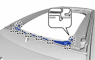
Using a brush or sponge, coat the application area of a new sliding roof seal with primer M.
Note:Do not apply too much primer M.
Allow the primer M to dry for 3 minutes or more.
Throw away any leftover primer M.
Tip:If an area other than specified is coated by accident, wipe off the primer M with a clean piece of cloth before it dries.
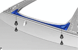
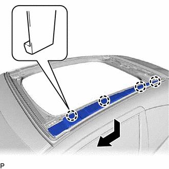
Install the sliding roof seal as shown in the illustration.
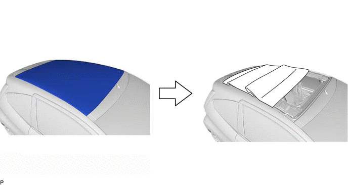
INSTALL ROOF WIND DEFLECTOR PANEL SUB-ASSEMBLY
-
Engage the 6 guides and 2 claws.
-
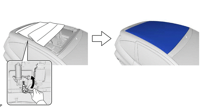
Using a T30 "TORX" socket wrench, install the roof wind deflector panel sub-assembly with the 2 clips.
-
INSTALL SLIDING ROOF GUIDE RAIL COVER LH
-
Engage the 4 claws as shown in the illustration.
-
Using a T30 "TORX" socket wrench, install the sliding roof guide rail cover LH the 2 clips.
-
INSTALL SLIDING ROOF GUIDE RAIL COVER RH
Tip:Use the same procedure as for the LH side.
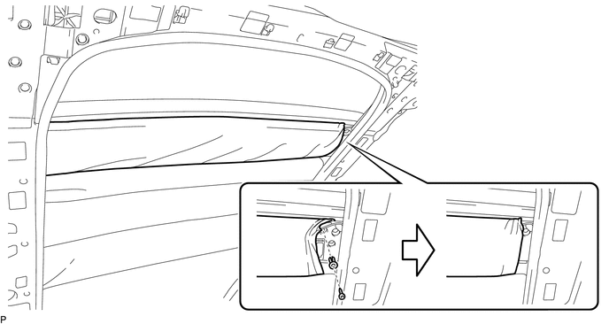
INSTALL CANVAS TOP TRIM SUB-ASSEMBLY
-
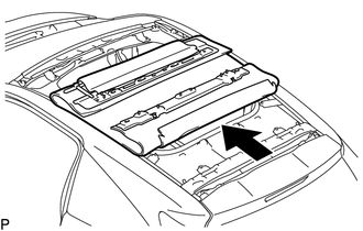
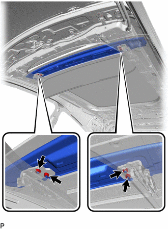
Insert the canvas top trim sub-assembly as shown in the illustration.
Using a T20 "TORX" socket wrench, install the 2 bolts.
2.7 N*m
28 kgf*cm
24 in.*lbf
-
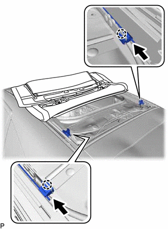
Engage the 2 claws as shown in the illustration.
Using an air riveter or hand riveter, install 2 new rivets.
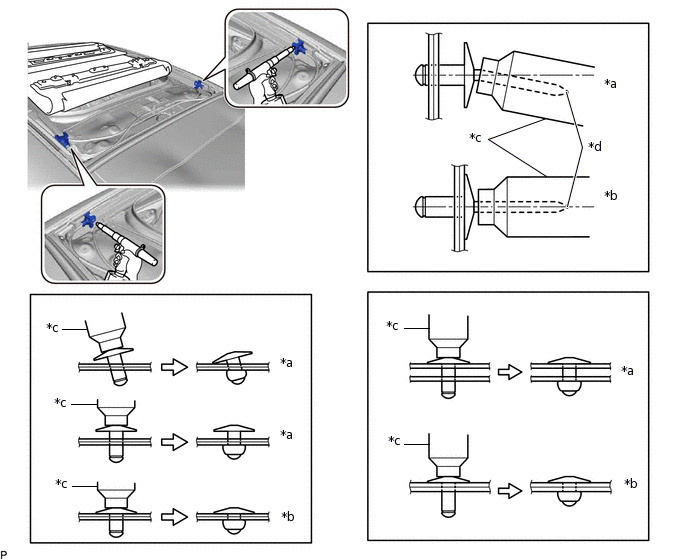
*a
Incorrect
*b
Correct
*c
Riveter
*d
Mandrel
Note:Do not pry on the rivets with the riveter, as this will cause damage to the riveter and mandrel.
Confirm that the rivets are seated properly against the canvas top trim sub-assembly.
Do not tilt the riveter when installing the rivets to the canvas top trim sub-assembly.
Do not leave any gaps between the rivet heads and canvas top trim sub-assembly.
Do not leave any gaps between the canvas top trim sub-assembly and canvas top panel. Firmly hold the canvas top trim sub-assembly and canvas top panel together while installing the rivets.
Tip:If the rivet cannot be cut, pull it once and cut it.
Using an air riveter or hand riveter, install 5 new rivets.
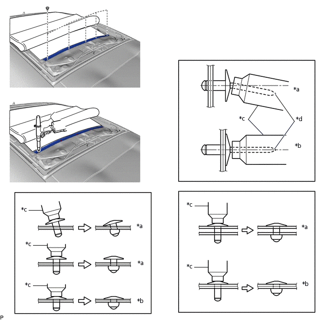
*a
Incorrect
*b
Correct
*c
Riveter
*d
Mandrel
Note:Do not pry on the rivets with the riveter, as this will cause damage to the riveter and mandrel.
Confirm that the rivets are seated properly against the canvas top trim sub-assembly.
Do not tilt the riveter when installing the rivets to the canvas top trim sub-assembly.
Do not leave any gaps between the rivet heads and canvas top trim sub-assembly.
Do not leave any gaps between the canvas top trim sub-assembly and canvas top panel. Firmly hold the canvas top trim sub-assembly and canvas top panel together while installing the rivets.
Tip:If the rivet cannot be cut, pull it once and cut it.
-
Return the canvas top trim sub-assembly as shown in the illustration.
-
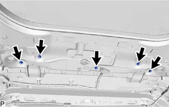
Temporarily install the 5 nuts.
-
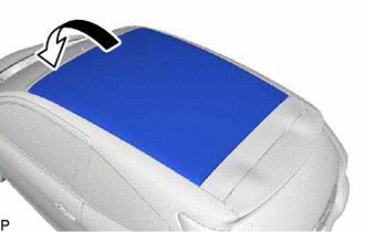
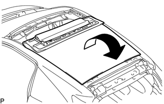
Return the canvas top trim sub-assembly as shown in the illustration.
Half open the canvas top trim sub-assembly as shown in the illustration.
-
Temporarily install canvas top trim sub-assembly with the 4 nuts.
Using a 6 mm straight hexagon wrench, close the canvas top trim sub-assembly as shown in the illustration.
Perform a level check.
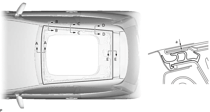
Check the difference in level for "a" between the roof panel and the upper surface of the canvas top panel when the canvas top trim sub-assembly is fully closed.
Tip:"+" represents the condition that the canvas top trim sub-assembly is above the panel level. "-" represents the condition that the canvas top trim sub-assembly is below the panel level.
Standard Dimension
Area
Measurement
Area
Measurement
A - A
-1.1 to 2.9 mm (-0.0433 to 0.144 in.)
B - B
-1.1 to 2.9 mm (-0.0433 to 0.144 in.)
C - C
-2.1 to 3.9 mm (-0.0827 to 0.154 in.)
D - D
-2.1 to 3.9 mm (-0.0827 to 0.154 in.)
E - E
-2.1 to 3.9 mm (-0.0827 to 0.154 in.)
-
-
Perform a gap check.
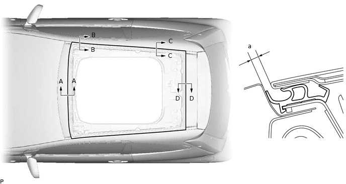
Check the gap in level for "a" between the roof panel and canvas top trim sub-assembly.
Standard Clearance
Area
Measurement
Area
Measurement
A - A
3.0 to 7.0 mm (0.118 to 0.276 in.)
B - B
2.0 to 8.0 mm (0.0787 to 0.315 in.)
C - C
2.0 to 8.0 mm (0.0787 to 0.315 in.)
D - D
2.0 to 8.0 mm (0.0787 to 0.315 in.)
Tighten the 5 bolts.
12 N*m
122 kgf*cm
9 ft.*lbf
Using a 6 mm straight hexagon wrench, half open the canvas top trim sub-assembly as shown in the illustration.
Tighten the 4 nuts to install the canvas top trim sub-assembly.
12 N*m
122 kgf*cm
9 ft.*lbf
Engage the guide and 6 claws to install the front fixation headliner cover LH.
Tip:Use the same procedure for the RH side and LH side.
Engage the hook.
Tip:Use the same procedure for the RH side and LH side.
Engage the 8 claws.
Using a T30 "TORX" socket wrench, install the clip as shown in the illustration.
 Tip:
Tip:Use the same procedure for the RH side and LH side.
-
Temporarily install the canvas top trim sub-assembly with the 2 bolts.
Install the canvas top trim sub-assembly.
-
TEMPORARILY TIGHTEN REAR SLIDING ROOF HOUSING MOUNTING BRACKET LH
Temporarily install the rear sliding roof housing mounting bracket LH with the 2 bolts.
TEMPORARILY TIGHTEN REAR SLIDING ROOF HOUSING MOUNTING BRACKET RH
Tip:Use the same procedure as for the LH side.
TEMPORARILY TIGHTEN NO. 1 SLIDING ROOF HOUSING BRACKET
Temporarily install the No. 1 sliding roof housing bracket with the 2 bolts.
Tip:Use the same procedure for the RH side and LH side.
TEMPORARILY TIGHTEN FRONT REMOVABLE ROOF HOUSING MOUNTING BRACKET LH
Temporarily install the front removable roof housing mounting bracket LH with the 2 bolts.
TEMPORARILY TIGHTEN FRONT REMOVABLE ROOF HOUSING MOUNTING BRACKET RH
Tip:Use the same procedure as for the LH side.
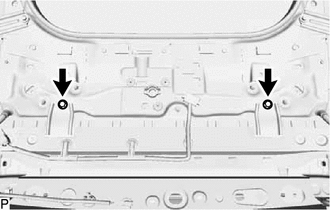
TIGHTEN SLIDING ROOF CANVAS SUB-ASSEMBLY
Temporarily install the sliding roof canvas sub-assembly with the 2 bolts.
Tighten the 14 bolts in the order shown in the illustration to install the sliding roof canvas sub-assembly.
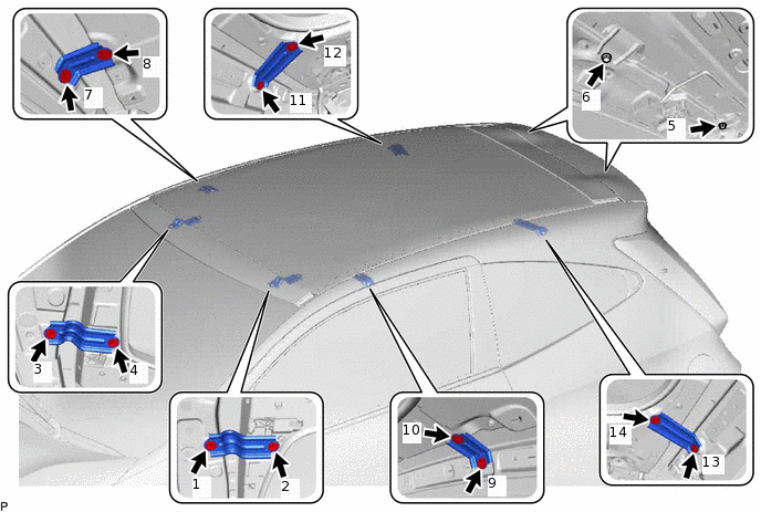
8.0 N*m
82 kgf*cm
71 in.*lbf
INSTALL CURTAIN SHIELD AIRBAG ASSEMBLY LH (w/ Curtain Shield Airbag)
INSTALL CURTAIN SHIELD AIRBAG ASSEMBLY RH (w/ Curtain Shield Airbag)
Tip:Use the same procedure as for the LH side.
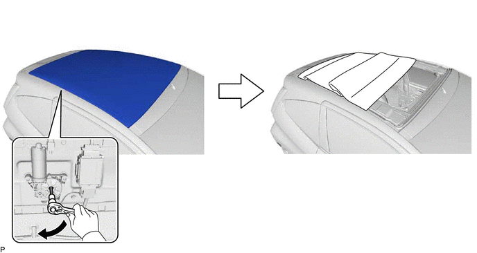
INSTALL SLIDE ROOF MOTOR ASSEMBLY
Clean the bolt hole on the canvas top panel.
Clean the bolt threads of the bolt.
Apply adhesive to the threads of the bolt.
Adhesive
Toyota Genuine Adhesive 1324, Three Bond 1324 or equivalent
Using a T25 "TORX" socket wrench, install the slide roof motor assembly with the 3 screws.
5.0 N*m
51 kgf*cm
44 in.*lbf
INSTALL SLIDING ROOF CONTROL ECU ASSEMBLY
-
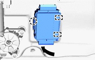
Engage the 2 guides and claw as shown in the illustration to install the sliding roof control ECU assembly.
-
INSTALL CANVAS TOP WIRE HARNESS
Engage the 2 claws.
Connect the connector to install the canvas top wire harness.
Engage the 2 claws and connect the connector.
CHECK FOR WATER LEAK
After adjusting the canvas top trim sub-assembly, check for water leakage into the vehicle interior.
If there are any leaks, adjust the canvas top trim sub-assembly.
INSTALL ROOF HEADLINING ASSEMBLY (for 3 Door)
INSTALL ROOF HEADLINING ASSEMBLY (for 5 Door)
RESET SLIDE ROOF MOTOR ASSEMBLY
CHECK SLIDING ROOF SYSTEM