SEAT HEATER SWITCH(for Rear) ON-VEHICLE INSPECTION
PROCEDURE
REMOVE NO. 2 AIR CONDITIONING CONTROL ASSEMBLY
Disconnect the No. 2 air conditioning control assembly connector.
-
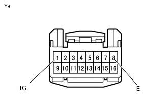
*a
Front view of wire harness connector
(to No. 2 Air Conditioning Control Assembly)
Measure the voltage according to the value(s) in the table below.
Standard Voltage
Tester Connection
Switch Condition
Specified Condition
1 (IG) - 8 (E)
Engine switch off
Below 1 V
1 (IG) - 8 (E)
Engine switch on (IG)
11 to 14 V
Measure the resistance according to the value(s) in the table below.
Standard Resistance
Tester Connection
Condition
Specified Condition
8 (E) - Body ground
Always
Below 1 Ω
If the result is not as specified, repair or replace the wire harness or connector.
Connect the No. 2 air conditioning control assembly connector.
-
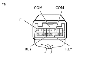
*a
Component with harness connected
(No. 2 Air Conditioning Control Assembly)
Measure the voltage according to the value(s) in the table below.
Standard Voltage
Tester Connection
Condition
Specified Condition
13 (RLY) - 8 (E)
Engine running, seat heater switch LH on
9 to 12 V
4 (COM) - 8 (E)
11 to 13 V
12 (RLY) - 8 (E)
Engine running, seat heater switch RH on
9 to 12 V
3 (COM) - 8 (E)
11 to 13 V
If the result is not as specified, replace the No. 2 air conditioning control assembly.