HEADUP DISPLAY SWITCH INSPECTION
PROCEDURE
-
INSPECT HEADUP DISPLAY SWITCH ASSEMBLY
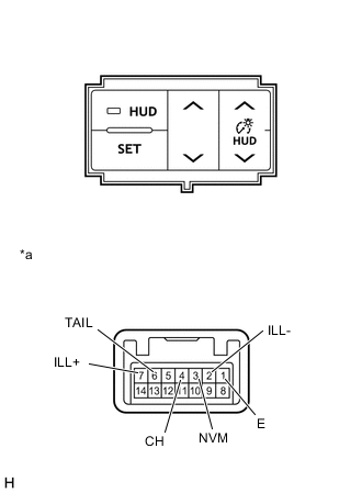
Text in Illustration *a Component without harness connected
(Headup Display Switch Assembly)
-
Measure the resistance according to the value(s) in the table below.
Standard Resistance Tester Connection Switch Condition Specified Condition 3 (NVM) - 1 (E) HUD SET switch is pressed 1782 to 1818 Ω HUD SET switch is not pressed 10 kΩ or higher HUD tilt up switch is pressed 811.8 to 828.2 Ω HUD tilt up switch is not pressed 10 kΩ or higher HUD tilt down switch is pressed 326.7 to 333.3 Ω HUD tilt down switch is not pressed 10 kΩ or higher 4 (CH) - 1 (E) HUD main switch is pressed 1782 to 1818 Ω HUD main switch is not pressed 10 kΩ or higher HUD rheostat up switch is pressed 811.8 to 828.2 Ω HUD rheostat up switch is not pressed 10 kΩ or higher HUD rheostat down switch is pressed 326.7 to 333.3 Ω HUD rheostat down switch is not pressed 10 kΩ or higher -
Apply auxiliary battery voltage from the wire harness back side between the terminals of the switch, and check the lighting condition of the headup display switch assembly.
OK Measurement Condition Condition Specified Condition Auxiliary battery positive (+) → 7 (ILL+)
Auxiliary battery negative (-) → 2 (ILL-)
Always Headup display switch assembly illuminates Auxiliary battery positive (+) → 6 (TAIL)
Auxiliary battery negative (-) → 1 (E)
Always HUD main switch illuminates If the result is not as specified, replace the headup display switch assembly.
-