BRAKE PEDAL(for RHD) INSTALLATION
PROCEDURE
INSTALL BRAKE PEDAL SUPPORT ASSEMBLY
-

Bolt

Nut
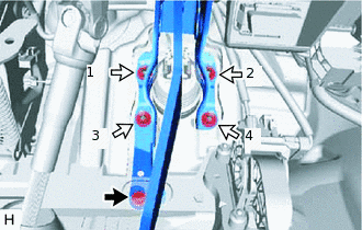
Install the brake pedal support assembly with the 4 nuts.
16 N*m
163 kgf*cm
12 ft.*lbf
Note:Tighten the 4 nuts in the order shown in the illustration.
Install the bolt to secure the brake pedal support assembly to the vehicle body.
14 N*m
143 kgf*cm
10 ft.*lbf
-
Install the bolt to secure the brake pedal support assembly to the instrument panel reinforcement assembly.
23.6 N*m
241 kgf*cm
17 ft.*lbf
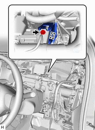
Engage the wire harness clamp to the brake pedal support assembly.
-
INSTALL PUSH ROD PIN
-
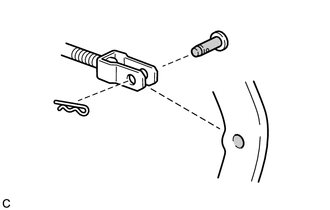

Lithium Soap Base Glycol Grease
Apply lithium soap base glycol grease to the push rod pin and installation hole of the brake pedal support assembly.
-
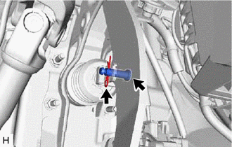
Connect the brake master cylinder push rod clevis to the brake pedal support assembly with the push rod pin as shown in the illustration and install a new clip.
Note:Install the push rod pin in the correct direction.
-
INSTALL STOP LIGHT SWITCH MOUNTING ADJUSTER
INSTALL STOP LIGHT SWITCH ASSEMBLY
INSTALL POWER STEERING ECU ASSEMBLY
INSTALL UPPER INSTRUMENT PANEL ASSEMBLY
INSPECT AND ADJUST BRAKE PEDAL