FRONT UPPER SUSPENSION ARM INSPECTION

CAUTION / NOTICE / HINT
Tech Tips
-
Use the same procedure for the RH and LH side.
-
The following procedure is for the LH side.
PROCEDURE
-
INSPECT FRONT UPPER NO. 1 SUSPENSION ARM ASSEMBLY LH
-
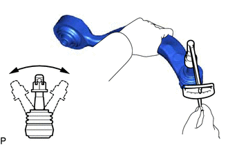
Inspect the turning torque of the ball joint.
-
Install the nut to the front upper No. 1 suspension arm assembly LH stud.
-
Using a torque wrench, turn the stud continuously at a rate of 2 to 4 seconds per turn and take the torque reading on the 5th turn.
Turning torque 0.98 to 3.43 N*m (10 to 34 kgf*cm, 9 to 30 in.*lbf) If the turning torque is not within the specified range, replace the front upper No. 1 suspension arm assembly LH with a new one.
-
-
Inspect the dust cover.
-
Check that the dust cover is not cracked and that there is no grease on it.
If the dust cover is cracked or there is grease on it, replace the front upper No. 1 suspension arm assembly LH with a new one.
-
-
-
INSPECT FRONT UPPER NO. 2 SUSPENSION ARM ASSEMBLY LH
-
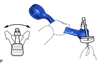
Inspect the turning torque of the ball joint.
-
Install the nut to the front upper No. 2 suspension arm assembly LH stud.
-
Using a torque wrench, turn the stud continuously at a rate of 2 to 4 seconds per turn and take the torque reading on the 5th turn.
Turning torque 0.98 to 3.43 N*m (10 to 34 kgf*cm, 9 to 30 in.*lbf) If the turning torque is not within the specified range, replace the front upper No. 2 suspension arm assembly LH with a new one.
-
-
Inspect the dust cover.
-
Check that the dust cover is not cracked and that there is no grease on it.
If the dust cover is cracked or there is grease on it, replace the front upper No. 2 suspension arm assembly LH with a new one.
-
-