REAR SUSPENSION MEMBER INSTALLATION
PROCEDURE
INSTALL CABLE SUPPORT BRACKET
Install the cable support bracket to the rear suspension member sub-assembly with the 2 bolts.
6.0 N*m
61 kgf*cm
53 in.*lbf
INSTALL REAR STABILIZER SUPPORT BRACKET LH
Install the rear stabilizer support bracket LH to the rear suspension member sub-assembly with the 4 bolts.
50 N*m
510 kgf*cm
37 ft.*lbf
INSTALL REAR STABILIZER SUPPORT BRACKET RH
Install the rear stabilizer support bracket RH to the rear suspension member sub-assembly with the 4 bolts.
50 N*m
510 kgf*cm
37 ft.*lbf
INSTALL REAR STABILIZER BUSHING
INSTALL REAR STABILIZER BAR
INSTALL REAR NO. 1 STABILIZER BAR BRACKET
INSTALL FRONT DIFFERENTIAL SUPPORT ASSEMBLY (for AWD)
INSTALL DIFFERENTIAL MOUNT CUSHION (for AWD)
INSTALL REAR TRACTION WITH TRANSAXLE MOTOR ASSEMBLY (for AWD)
INSTALL REAR SUSPENSION MEMBER SUB-ASSEMBLY
-
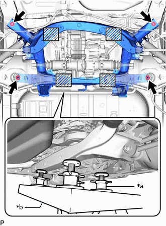
*a
Plate Lift Attachment
*b
Engine Lifter

Attachment Placement Positions
Place wooden blocks or plate lift attachments on an engine lifter, and then set the rear suspension member sub-assembly so that the attachments are in the positions shown in the illustration.
Note:Place the wooden blocks or plate lift attachments so that the rear suspension member sub-assembly is level.
As the rear suspension member sub-assembly is very heavy, be sure to support it securely.
Install the rear suspension member and 2 rear upper body mounting cushions with the 2 bolts and 2 nuts.
125 N*m
1275 kgf*cm
92 ft.*lbf
-
CONNECT WIRE HARNESS
-
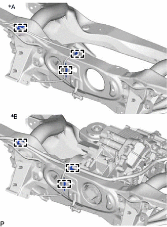
*A
for 2WD
*B
for 4WD
Attach the 3 clamps and connect the wire harness.
-
INSTALL EXHAUST TAILPIPE ASSEMBLY
TEMPORARILY INSTALL REAR NO. 2 SUSPENSION ARM ASSEMBLY LH
TEMPORARILY INSTALL REAR NO. 2 SUSPENSION ARM ASSEMBLY RH
Tip:Use the same procedure described for the LH side.
TEMPORARILY INSTALL REAR NO. 1 SUSPENSION ARM ASSEMBLY LH
TEMPORARILY INSTALL REAR NO. 1 SUSPENSION ARM ASSEMBLY RH
Tip:Use the same procedure described for the LH side.
TEMPORARILY INSTALL REAR UPPER CONTROL ARM ASSEMBLY LH
TEMPORARILY INSTALL REAR UPPER CONTROL ARM ASSEMBLY RH
Tip:Use the same procedure described for the LH side.
TEMPORARILY INSTALL REAR SHOCK ABSORBER ASSEMBLY LH
TEMPORARILY INSTALL REAR SHOCK ABSORBER ASSEMBLY RH
Tip:Use the same procedure described for the LH side.
INSTALL REAR AXLE CARRIER SUB-ASSEMBLY LH
INSTALL REAR AXLE CARRIER SUB-ASSEMBLY RH
Tip:Use the same procedure described for the LH side.
TEMPORARILY INSTALL REAR NO. 2 SUSPENSION ARM ASSEMBLY LH
TEMPORARILY INSTALL REAR NO. 2 SUSPENSION ARM ASSEMBLY RH
Tip:Use the same procedure described for the LH side.
CONNECT REAR TRAILING ARM ASSEMBLY LH
CONNECT REAR TRAILING ARM ASSEMBLY RH
Tip:Use the same procedure described for the LH side.
TEMPORARILY INSTALL REAR NO. 1 SUSPENSION ARM ASSEMBLY LH
TEMPORARILY INSTALL REAR NO. 1 SUSPENSION ARM ASSEMBLY RH
Tip:Use the same procedure described for the LH side.
INSTALL REAR HEIGHT CONTROL SENSOR SUB-ASSEMBLY LH
STABILIZE SUSPENSION
TIGHTEN REAR UPPER CONTROL ARM ASSEMBLY LH
TIGHTEN REAR UPPER CONTROL ARM ASSEMBLY RH
Tip:Use the same procedure described for the LH side.
TIGHTEN REAR NO. 2 SUSPENSION ARM ASSEMBLY LH
TIGHTEN REAR NO. 2 SUSPENSION ARM ASSEMBLY RH
Tip:Use the same procedure described for the LH side.
TIGHTEN REAR NO. 1 SUSPENSION ARM ASSEMBLY LH
TIGHTEN REAR NO. 1 SUSPENSION ARM ASSEMBLY RH
Tip:Use the same procedure described for the LH side.
TIGHTEN REAR SHOCK ABSORBER ASSEMBLY LH
TIGHTEN REAR SHOCK ABSORBER ASSEMBLY RH
Tip:Use the same procedure described for the LH side.
CONNECT PARKING BRAKE ASSEMBLY LH
CONNECT PARKING BRAKE ASSEMBLY RH
Tip:Use the same procedure described for the LH side.
CONNECT PARKING BRAKE CABLE
Connect the No. 2 parking brake cable assembly and No. 3 parking brake cable assembly with the 6 bolts.
6.0 N*m
61 kgf*cm
53 in.*lbf
INSTALL REAR SUSPENSION MEMBER BRACE LH
Install the rear suspension member brace LH to the front suspension crossmember sub-assembly with the 3 bolts.
35 N*m
357 kgf*cm
26 ft.*lbf
INSTALL REAR SUSPENSION MEMBER BRACE RH
Tip:Use the same procedure described for the LH side.
INSTALL REAR STABILIZER LINK ASSEMBLY LH
INSTALL REAR STABILIZER LINK ASSEMBLY RH
Tip:Use the same procedure described for the LH side.
INSTALL REAR AXLE HUB AND BEARING ASSEMBLY LH
for 2WD:Click here
for 4WD:Click here
INSTALL REAR AXLE HUB AND BEARING ASSEMBLY RH
Tip:Use the same procedure described for the LH side.
INSTALL REAR DISC
CONNECT REAR DISC BRAKE CALIPER ASSEMBLY LH
CONNECT REAR DISC BRAKE CALIPER ASSEMBLY RH
Tip:Use the same procedure described for the LH side.
INSTALL REAR AXLE SHAFT NUT LH (for AWD)
INSTALL REAR AXLE SHAFT NUT RH (for AWD)
Tip:Use the same procedure described for the LH side.
INSPECT REAR AXLE HUB BEARING LOOSENESS
INSPECT REAR AXLE HUB RUNOUT
STAKE REAR AXLE SHAFT NUT LH (for AWD)
STAKE REAR AXLE SHAFT NUT RH (for AWD)
Tip:Use the same procedure described for the LH side.
CONNECT SKID CONTROL SENSOR WIRE LH (for 2WD)
CONNECT SKID CONTROL SENSOR WIRE RH (for 2WD)
Tip:Use the same procedure described for the LH side.
CONNECT REAR SPEED SENSOR LH (for AWD)
CONNECT REAR SPEED SENSOR RH (for AWD)
Tip:Use the same procedure described for the LH side.
INSTALL REAR SUSPENSION ARM COVER LH (w/ Cover)
INSTALL REAR SUSPENSION ARM COVER RH (w/ Cover)
Tip:Use the same procedure described for the LH side.
CONNECT WIRE HARNESS (for AWD)
INSTALL SERVICE PLUG GRIP (for AWD)
INSTALL REAR WHEEL
INSPECT AND ADJUST REAR WHEEL ALIGNMENT
CHECK FOR SPEED SENSOR SIGNAL
HEIGHT CONTROL SENSOR SIGNAL INITIALIZATION
PERFORM INITIALIZATION