AUDIO AND VISUAL SYSTEM Steering Pad Switch Circuit
DESCRIPTION
This circuit sends an operation signal from the steering pad switch to the radio and display receiver assembly.
If there is an open in the circuit, the audio system cannot be operated using the steering pad switch.
If there is a short in the circuit, the same condition as when a switch is continuously depressed occurs.
Therefore, the radio and display receiver assembly cannot be operated using the steering pad switch, also the radio and display receiver assembly itself will not function.
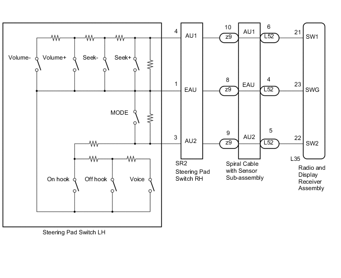
WIRING DIAGRAM
CAUTION / NOTICE / HINT
Note
The vehicle is equipped with a Supplemental Restraint System (SRS) which includes components such as airbags. Before servicing (including removal or installation of parts), be sure to read the precaution for Supplemental Restraint System Click here.
PROCEDURE
-
CHECK HARNESS AND CONNECTOR (STEERING PAD SWITCH SIGNAL)
-
Disconnect the L35 radio and display receiver assembly connector.
-
Measure the resistance according to the value(s) in the table below.
Standard Resistance Tester Connection Condition Specified Condition L35-21 (SW1) - L35-23 (SWG) No switch pushed 95 to 105 kΩ Seek+ switch pushed Below 2.5 Ω Seek- switch pushed 323 to 335 Ω Volume+ switch pushed 980 to 1020 Ω Volume- switch pushed 3048 to 3172 Ω L35-22 (SW2) - L35-23 (SWG) No switch pushed 95 to 105 kΩ MODE switch pushed Below 2.5 Ω On hook switch pushed 323 to 335 Ω Off hook switch pushed 980 to 1020 Ω Voice switch pushed 3048 to 3172 Ω
OK 
PROCEED TO NEXT SUSPECTED AREA SHOWN IN PROBLEM SYMPTOMS TABLE Click here
NG 
-
-
INSPECT STEERING PAD SWITCH
-
Remove the steering pad switch (w/o TFT Display) Click here.
-
Remove the steering pad switch (w/ TFT Display) Click here.
-
Measure the resistance according to the value(s) in the table below.
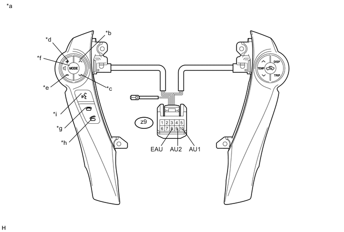
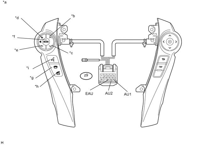
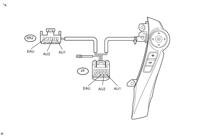
Standard Resistance Tester Connection Condition Specified Condition z9-10 (AU1) - z9-8 (EAU) No switch pushed 95 to 105 kΩ Seek+ switch pushed Below 2.5 Ω Seek- switch pushed 323 to 335 Ω Volume+ switch pushed 980 to 1020 Ω Volume- switch pushed 3048 to 3172 Ω z9-9 (AU2) - z9-8 (EAU) No switch pushed 95 to 105 kΩ MODE switch pushed Below 2.5 Ω On hook switch pushed 323 to 335 Ω Off hook switch pushed 980 to 1020 Ω Voice switch pushed 3048 to 3172 Ω Text in Illustration *a Component without harness connected
(Steering Pad Switch)
*b Seek+ *c Seek- *d Volume+ *e Volume- *f MODE *g On hook *h Off hook *i Voice - - -
Proceed to the next step based on the inspection result.
Result Result Proceed to NG A OK B
B 
INSPECT SPIRAL CABLE WITH SENSOR SUB-ASSEMBLY Click here
A
-
-
INSPECT STEERING PAD SWITCH RH
-
Disconnect the steering pad switch RH connectors (w/o TFT Display).
-
Disconnect the steering pad switch RH connectors (w/ TFT Display).
-
Measure the resistance according to the value(s) in the table below.
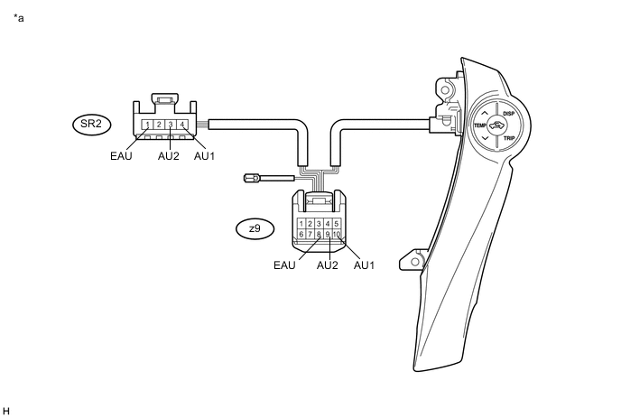
Standard Resistance Tester Connection Condition Specified Condition SR2-4 (AU1) - z9-10 (AU1) Always Below 2.5 Ω SR2-3 (AU2) - z9-9 (AU2) Always Below 2.5 Ω SR2-1 (EAU) - z9-8 (EAU) Always Below 2.5 Ω Text in Illustration *a Component without harness connected
(Steering Pad Switch RH)
- -
OK
REPLACE STEERING PAD SWITCH LH Click here
NG
REPLACE STEERING PAD SWITCH RH Click here
-
-
INSPECT SPIRAL CABLE WITH SENSOR SUB-ASSEMBLY
-
Remove the spiral cable with sensor sub-assembly Click here.
-
Measure the resistance according to the value(s) in the table below.
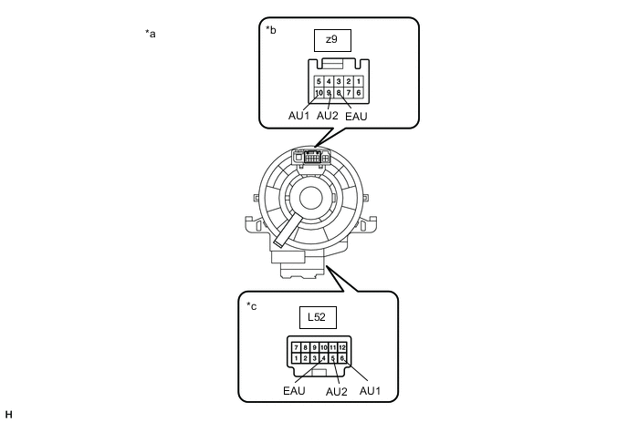
Standard Resistance Tester Connection Condition Specified Condition z9-8 (EAU) - L52-4 (EAU) Center 3 Ω or less 2.5 rotations to the left 2.5 rotations to the right z9-10 (AU1) - L52-6 (AU1) Center 3 Ω or less 2.5 rotations to the left 2.5 rotations to the right z9-9 (AU2) - L52-5 (AU2) Center 3 Ω or less 2.5 rotations to the left 2.5 rotations to the right -
After setting the spiral cable with sensor sub-assembly to the center position, rotate the spiral cable with sensor sub-assembly 2.5 times clockwise. Then while rotating the spiral cable with sensor sub-assembly 5 times counterclockwise, measure the resistance according to the value(s) in the table below.
Standard Resistance Tester Connection Condition Specified Condition z9-8 (EAU) - L52-4 (EAU) Always 3 Ω or less z9-10 (AU1) - L52-6 (AU1) Always 3 Ω or less z9-9 (AU2) - L52-5 (AU2) Always 3 Ω or less Note
-
Press and hold the lock located in the center of the spiral cable with sensor sub-assembly to rotate the spiral cable with sensor sub-assembly.
-
The spiral cable with sensor sub-assembly is an important part of the SRS airbag system. Incorrect removal or installation of the spiral cable with sensor sub-assembly may prevent the airbag from deploying.
-
As the spiral cable with sensor sub-assembly may break, do not rotate the spiral cable with sensor sub-assembly more than the specified amount.
Text in Illustration *a Component without harness connected
(Spiral Cable with Sensor Sub-assembly)
*b Steering Pad Switch Side *c Vehicle Side -
OK
REPAIR OR REPLACE HARNESS OR CONNECTOR (RADIO AND DISPLAY RECEIVER ASSEMBLY - SPIRAL CABLE WITH SENSOR SUB-ASSEMBLY)
NG
REPLACE SPIRAL CABLE WITH SENSOR SUB-ASSEMBLY Click here
-