ENGINE UNIT INSTALLATION

PROCEDURE
-
INSTALL IDLER PULLEY SUB-ASSEMBLY
-
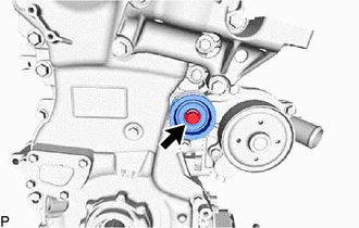
Install the idler pulley sub-assembly to the timing chain cover assembly with the bolt.
- Torque:
- 43 N*m { 438 kgf*cm, 32 ft.*lbf }
-
-
INSTALL V-RIBBED BELT TENSIONER ASSEMBLY
-
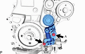
Temporarily install the V-ribbed belt tensioner assembly to the timing chain cover assembly with the 2 bolts.
-
Tighten the bolt (A).
- Torque:
- 21 N*m { 214 kgf*cm, 15 ft.*lbf }
-
Tighten the bolt (B).
- Torque:
- 21 N*m { 214 kgf*cm, 15 ft.*lbf }
-
-
INSTALL OIL FILLER CAP GASKET
-
Install the oil filler cap gasket to the oil filler cap sub-assembly.
-
-
INSTALL OIL FILLER CAP SUB-ASSEMBLY
-
Install the oil filler cap sub-assembly to the cylinder head cover sub-assembly.
-
-
INSTALL WIRE HARNESS CLAMP BRACKET
-
Install the 2 wire harness clamp brackets to the cylinder head cover sub-assembly with the 2 bolts.
- Torque:
- 8.0 N*m { 82 kgf*cm, 71 in.*lbf }
-
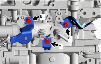
Install the 3 wire harness clamp brackets to the cylinder head sub-assembly with the 3 bolts.
- Torque:
- Bolt (A)
- 8.0 N*m { 82 kgf*cm, 71 in.*lbf }
- Bolt (B)
- 12.5 N*m { 127 kgf*cm, 9 ft.*lbf }
-
-
INSTALL ENGINE WIRE
-
Install the engine wire to the engine assembly with transaxle.
-
-
INSTALL TURBOCHARGER SUB-ASSEMBLY
-
CONNECT INLET TURBO OIL PIPE SUB-ASSEMBLY
-
INSTALL EXHAUST MANIFOLD CONVERTER SUB-ASSEMBLY
-
INSTALL NO. 2 EXHAUST MANIFOLD HEAT INSULATOR
-
INSTALL NO. 1 EXHAUST MANIFOLD HEAT INSULATOR
-
INSTALL NO. 1 VACUUM PIPE (w/ Differential Pressure Sensor)
-
INSTALL IGNITION COIL ASSEMBLY
-
INSTALL INTAKE MANIFOLD WITH INTERCOOLER ASSEMBLY AND THROTTLE WITH MOTOR BODY ASSEMBLY
-
Install 2 new No. 1 intake manifold to head gaskets to the intake manifold.
-
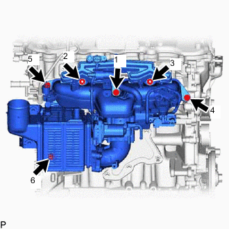
Temporarily install the intake manifold with intercooler assembly and throttle with motor body assembly with the 4 bolts and 2 nuts.
-
Tighten the 4 bolts and 2 nuts in the order shown in the illustration.
- Torque:
- 21 N*m { 214 kgf*cm, 15 ft.*lbf }
-
-
INSTALL STUD BOLT
-
Using E8 "TORX" socket wrenches, install the stud bolt.
- Torque:
- 9.0 N*m { 92 kgf*cm, 80 in.*lbf }
-
-
INSTALL FUEL PUMP PROTECTOR
-
INSTALL NO. 2 VENTILATION HOSE
-
CONNECT NO. 1 WATER BY-PASS HOSE AND NO. 2 WATER BY-PASS HOSE
-
Connect the No. 1 water by-pass hose to the cylinder head sub-assembly and slide the clamp to secure it.
-
Connect the No. 2 water by-pass hose to the No. 1 water by-pass pipe and slide the clamp to secure it.
-
-
CONNECT VACUUM TRANSMITTING HOSE ASSEMBLY
-
CONNECT NO. 2 VACUUM TRANSMITTING HOSE ASSEMBLY
-
INSTALL PURGE VALVE (PURGE VSV)
-
CONNECT ENGINE WIRE
-
INSTALL NO. 2 WATER BY-PASS PIPE
-
INSTALL NO. 1 COMPRESSOR MOUNTING BRACKET
-
Install the 2 stud bolts to the cylinder block sub-assembly and stiffening crankcase assembly.
- Torque:
- 9.0 N*m { 92 kgf*cm, 80 in.*lbf }
-
Install the No. 1 compressor mounting bracket with the 2 bolts and 2 nuts.
- Torque:
- 21 N*m { 214 kgf*cm, 15 ft.*lbf }
-
-
INSTALL COMPRESSOR ASSEMBLY WITH PULLEY
-
INSTALL GENERATOR ASSEMBLY
-
INSTALL V-RIBBED BELT
-
INSTALL DRIVE SHAFT BEARING BRACKET (for 2WD)
-
Install the drive shaft bearing bracket to the cylinder block sub-assembly and stiffening crankcase assembly with the 3 bolts.
- Torque:
- 63.7 N*m { 650 kgf*cm, 47 ft.*lbf }
Note
Make sure that the bolts and bolt holes are free of oil. Clean them if necessary.
-
-
INSTALL NO. 2 TRANSFER STIFFENER PLATE (for AWD)
-
Install the No. 2 transfer stiffener plate to the cylinder block sub-assembly and stiffening crankcase assembly with the 3 bolts.
- Torque:
- 64 N*m { 653 kgf*cm, 47 ft.*lbf }
-