FRONT DIFFERENTIAL CARRIER ASSEMBLY DISASSEMBLY
-
INSPECT DIFFERENTIAL RING GEAR AND DIFFERENTIAL DRIVE PINION BACKLASH
-
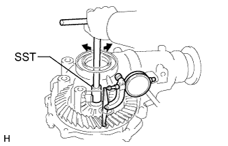
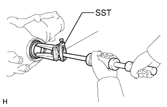
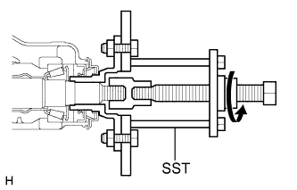
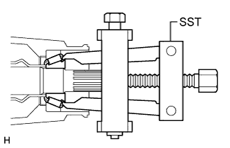
Using SST and a dial indicator, measure the ring gear backlash.
- SST
- 09564-33010
Backlash 0.11 to 0.21 mm (0.00433 to 0.00826 in.)
-
If the backlash is not as specified, adjust the side bearing preload or perform repairs as necessary.
Tech Tips
Perform the measurement at 3 or more positions around the circumference of the ring gear.
-
-
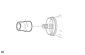
INSPECT FRONT DRIVE PINION COMPANION FLANGE SUB-ASSEMBLY
-
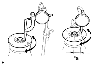
Text in Illustration *a 30 mm (1.18 in.) Using a dial indicator, measure the runout of the companion flange vertically and laterally.
Maximum Runout Item Specified Condition Vertical runout 0.10 mm (0.00394 in.) Lateral runout 0.10 mm (0.00394 in.)
-
If the runout is more than the maximum, replace the companion flange.
-
-
-
REMOVE DIFFERENTIAL VACUUM ACTUATOR ASSEMBLY
-
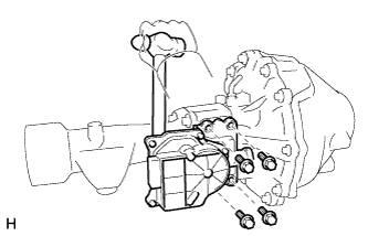
Remove the 4 bolts.
-
Using a hammer, pry out the actuator from the differential tube.
-
-
REMOVE FRONT DIFFERENTIAL TUBE ASSEMBLY
-
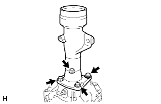
Remove the 4 bolts.
-
Using a plastic-faced hammer, tap out the differential tube.
-
-
REMOVE DIFFERENTIAL SIDE GEAR SHAFT OIL SEAL LH
-
Using SST, tap out the oil seal.
- SST
- 09308-00010
-
-
REMOVE DIFFERENTIAL CLUTCH SLEEVE
-
Remove the differential clutch sleeve.
-
-
REMOVE DIFFERENTIAL SIDE GEAR INTER SHAFT SUB-ASSEMBLY
-
Remove the snap ring from the inter shaft.
-
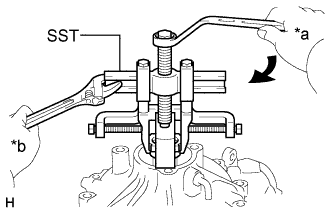
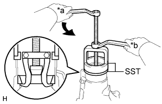
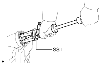
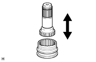
Text in Illustration *a Turn *b Hold Using SST, remove the inter shaft.
- SST
- 09350-20015 ( 09369-20040 )
- 09950-40011 ( 09951-04010, 09952-04010, 09953-04020, 09954-04010, 09955-04011, 09957-04010, 09958-04011 )
-
-
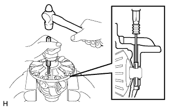
REMOVE FRONT DIFFERENTIAL SIDE BEARING RETAINER DEFLECTOR
-
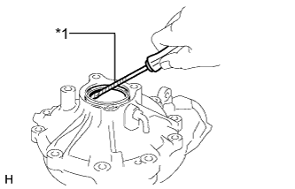
Text in Illustration *1 Protective Tape Using a screwdriver, pry out the bearing retainer deflector.
Tech Tips
Tape the screwdriver tip before use.
-
-
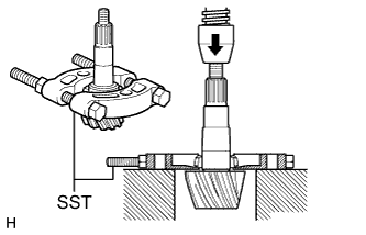
REMOVE FRONT DRIVE PINION COMPANION FLANGE NUT
-
Using SST and a hammer, loosen the staked part of the nut.
- SST
- 09930-00010 ( 09931-00010, 09931-00020 )
-
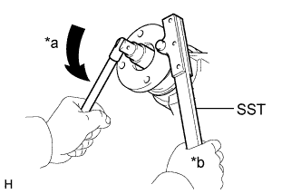
Text in Illustration *a Turn *b Hold Using SST to hold the companion flange, remove the nut.
- SST
- 09330-00021 ( 09330-00030 )
-
-
REMOVE FRONT DRIVE PINION COMPANION FLANGE SUB-ASSEMBLY WITH DUST DEFLECTOR
-
Using SST, remove the companion flange with dust deflector.
- SST
- 09950-30012 ( 09951-03010, 09953-03010, 09954-03010, 09955-03030, 09956-03020 )
Note
Before using SST (center bolt), apply hypoid gear oil to its threads and tip.
-
-
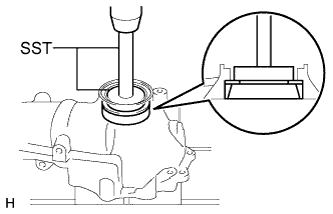
REMOVE FRONT DIFFERENTIAL CARRIER OIL SEAL
-
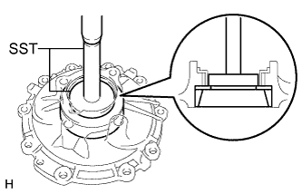
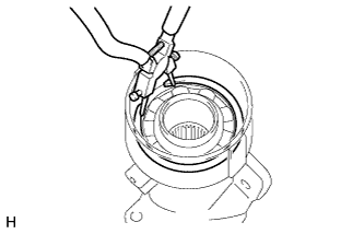
Text in Illustration *1 Oil Seal *2 Oil Slinger Using SST, remove the oil seal.
- SST
- 09308-10010
-
-
REMOVE FRONT DIFFERENTIAL DRIVE PINION OIL SLINGER
-
Remove the oil slinger from the drive pinion.
-
-
REMOVE FRONT DRIVE PINION REAR TAPERED ROLLER BEARING
-
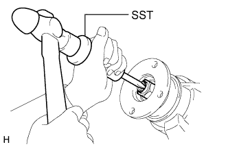
Using SST, remove the roller bearing (inner) from the drive pinion.
- SST
- 09556-22010
-
-
REMOVE DIFFERENTIAL SIDE BEARING RETAINER
-
Remove the 10 bolts and tap out the retainer with a plastic-faced hammer.
-
-
REMOVE DIFFERENTIAL CASE ASSEMBLY
-
REMOVE DIFFERENTIAL DRIVE PINION
-
REMOVE FRONT DIFFERENTIAL DRIVE PINION BEARING SPACER
-
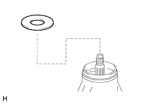
Remove the bearing spacer from the drive pinion.
-
-
REMOVE FRONT DRIVE PINION FRONT TAPERED ROLLER BEARING
-
Using SST and a press, press out the roller bearing (inner) and drive pinion plate washer from the drive pinion.
- SST
- 09950-00020
Note
Do not drop the drive pinion.
Tech Tips
If the drive pinion or ring gear is damaged, replace them as a set.
-
-
REMOVE FRONT DRIVE PINION FRONT TAPERED ROLLER BEARING
-
Using a brass bar and hammer, tap out the roller bearing (outer).
-
-
REMOVE FRONT DRIVE PINION REAR TAPERED ROLLER BEARING
-
Text in Illustration *a Turn *b Hold Using SST, remove the roller bearing (outer).
- SST
- 09502-12010
- 09612-65014 ( 09612-01020, 09612-01050 )
-
-
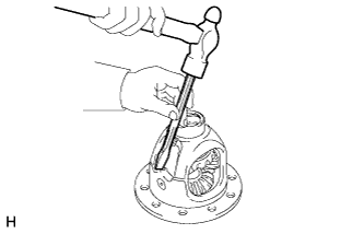
REMOVE FRONT DIFFERENTIAL OIL STORAGE RING
-
Using a brass bar and hammer, tap out the oil storage ring.
-
-
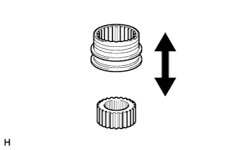
REMOVE FRONT DIFFERENTIAL CASE BEARING
Tech Tips
-
Measure the thickness of the case washer.
-
Tag the bearing outer races so that they can be reinstalled in the correct locations.
-
Using SST and a press, press out the case bearing (outer) and plate washer from the bearing retainer.
- SST
- 09950-60020 ( 09951-00680 )
- 09950-70010 ( 09951-07150 )
-
If the bearing is damaged during removal, replace it.
-
Using SST and a press, press out the case bearing (outer) and plate washer from the differential carrier.
- SST
- 09950-60020 ( 09951-00680 )
- 09950-70010 ( 09951-07150 )
-
If the bearing is damaged during removal, replace it.
-
-
REMOVE DIFFERENTIAL RING GEAR
-
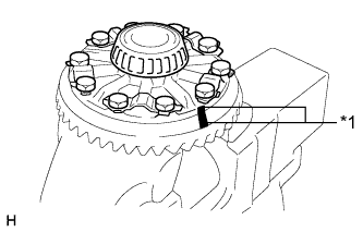
Text in Illustration *1 Matchmark Place matchmarks on the ring gear and differential case.
-
Remove the 10 ring gear set bolts.
-
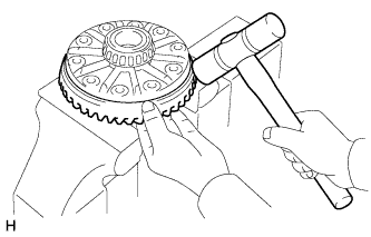
Using a plastic-faced hammer, tap on the ring gear to separate it from the differential case.
-
-
REMOVE FRONT DIFFERENTIAL CASE BEARING
Tech Tips
The differential case and case bearings should only be removed when replacement is necessary.
-
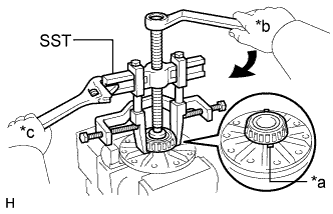
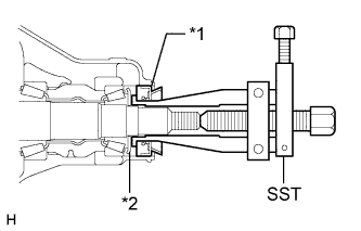
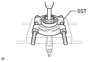
Text in Illustration *a Notch *b Turn *c Hold Using SST, remove the 2 case bearings (inner) from the differential case.
- SST
- 09950-60010 ( 09951-00480 )
- 09950-40011 ( 09951-04020, 09952-04010, 09953-04030, 09954-04010, 09955-04061, 09953-04020, 09958-04011 )
Tech Tips
Attach the claws of SST to the notch in the differential case assembly to secure SST.
-
-
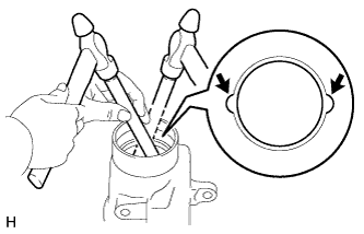
DISASSEMBLE DIFFERENTIAL CASE
-
Using a chisel and hammer, unstake the differential case.
-
Using a pin punch and hammer, tap out the straight pin.
-
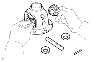
Remove the following parts from the differential case.
-
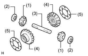
(1) Differential pinion gear (2 pieces)
-
(2) Differential pinion gear thrust washer (2 pieces)
-
(3) Differential pinion shaft
-
(4) Differential side gear (2 pieces)
-
(5) Differential side gear thrust washer (2 pieces)
-
-
-
INSPECT DIFFERENTIAL GEAR KIT
-
Check that the differential pinion and differential side gear are not damaged.
-
If the differential pinion or differential side gear is damaged, replace the differential gear kit.
-
-
-
INSPECT FRONT DIFFERENTIAL CASE
-
Check that the differential case is not damaged.
-
If the differential case is damaged, replace it.
-
-
-
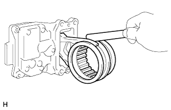
REMOVE FRONT DIFFERENTIAL SIDE GEAR NEEDLE ROLLER BEARING
-
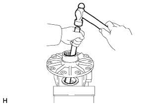
Using a brass bar and hammer, tap out the 2 bearings.
-
-
REMOVE DIFFERENTIAL CLUTCH HUB
-
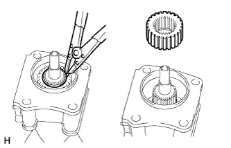
Using a snap ring expander, remove the snap ring.
-
Remove the differential clutch hub.
-
-
REMOVE DIFFERENTIAL SIDE GEAR SHAFT OIL SEAL RH
-
Using SST, tap out the oil seal from the differential tube.
- SST
- 09308-00010
-
-
REMOVE DIFFERENTIAL SIDE GEAR SHAFT SUB-ASSEMBLY RH
-
Using a snap ring expander, remove the snap ring.
-
Remove the shaft from the differential tube.
-
-
REMOVE FRONT DIFFERENTIAL SIDE GEAR SHAFT RH BEARING
-
Using a snap ring expander, remove the snap ring.
-
Using SST, a brass bar and a press, press out the shaft RH bearing.
- SST
- 09950-00020
Note
-
Do not damage the bearing.
-
Do not drop the shaft.
-
-
INSPECT DIFFERENTIAL CLUTCH SLEEVE AND DIFFERENTIAL CLUTCH HUB
-
Check that there is no wear or damage on the clutch hub and clutch sleeve.
-
If necessary, replace them.
-
-
Check that the clutch sleeve slides smoothly on the clutch hub.
-
-
INSPECT DIFFERENTIAL CLUTCH SLEEVE AND DIFFERENTIAL SIDE GEAR INTER SHAFT
-
Check that there is no wear or damage on the clutch sleeve and side gear inter shaft.
If necessary, replace clutch sleeve and side gear inter shaft.
-
Check that clutch sleeve slides smoothly on the side gear inter shaft.
-
-
INSPECT DIFFERENTIAL CLUTCH SLEEVE AND CLUTCH SLEEVE FORK CLEARANCE
-
Using a feeler gauge, measure the clearance between the sleeve fork and clutch sleeve.
Maximum clearance 0.35 mm (0.0138 in.)
-
If the clearance is more than the maximum, replace the fork or clutch sleeve.
-
-