COMBUSTION TYPE POWER HEATER SYSTEM DIAGNOSIS SYSTEM
The cause of malfunctions (such as abnormal voltage, overheat, a short-circuit, breaking of functional components, etc.) can be checked by connecting the DTC tester and reading DTCs.
DIAGNOSTICS FUNCTION
Turn the ignition switch off.
Disconnect the A42 heater assembly connector.
Connect connector A of the DTC tester to the vehicle wire harness, and connector B of the DTC tester to the heater assembly connector.
Start the engine.
Press the D DTC calling button to display 3-digit DTCs.
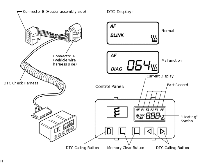
DESCRIPTION OF DISPLAY AND BUTTONS
AF: Current Malfunction (Blinks when there is a current malfunction)
DIAG: DTC (Example: 064 Flame sensor malfunction)
Memory clear buttons: Clears DTCs (Press both buttons simultaneously for more than 2 seconds.)
> DTC calling button: Scrolls up DTCs (5 history codes can be stored.)
< DTC calling button: Scrolls down DTCs (5 history codes can be stored.)
FAULTY MEMORY
The ECU is able to store up to 5 DTCs in memory. If it is full, new data is written over F5.
FAIL-SAFE
If the glow plug breaks, the ECU detects the breakage and stops the automatic operation to prevent combustion heater operation.