FRONT SUSPENSION MEMBER INSTALLATION

PROCEDURE
-
INSTALL HOLE PLUG
-
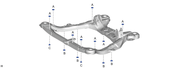
for Type A:
-
Install the 14 hole plugs to the front frame assembly.
Tech Tips
There are 3 different shapes of hole plug.
-
-
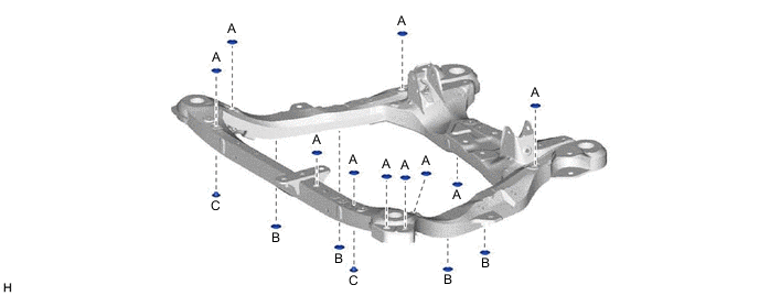
for Type B:
-
Install the 16 hole plugs to the front frame assembly.
Tech Tips
There are 3 different shapes of hole plug.
-
-
-
INSTALL FRONT SUSPENSION MEMBER BODY MOUNTING REAR CUSHION LH
-
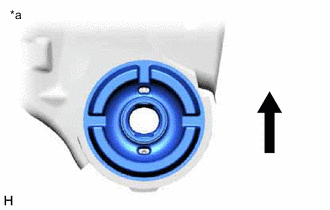
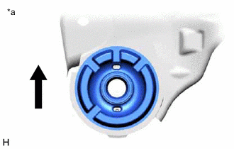
*a View from Underneath 
Front of the Vehicle Align a new front suspension member body mounting rear cushion LH as shown in the illustration and set it to the front frame assembly.
Note
-
Position the front suspension member body mounting rear cushion LH in the correct direction.
-
Do not apply lubricant to the outer sleeve of the front suspension member body mounting rear cushion LH.
-
-

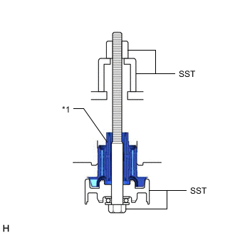
*1 Front Suspension Member Body Mounting Rear Cushion LH Install SST as shown in the illustration.
- SST
- 09830-10010 ( 09830-01010, 09830-01020, 09830-01030, 09830-01060 )
Note
Be sure to install SST (09830-01030) in the correct direction.
-
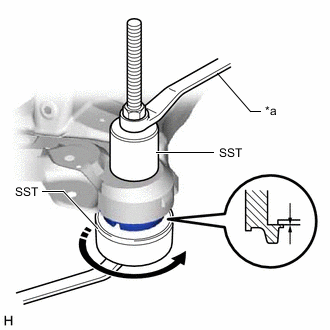
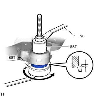
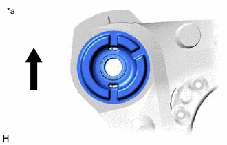
*a Hold 
Turn Using SST, install the front suspension member body mounting rear cushion LH as shown in the illustration.
Note
Check that there is no clearance between the front frame assembly and the front suspension member body mounting rear cushion LH.
-
-
INSTALL FRONT SUSPENSION MEMBER BODY MOUNTING REAR CUSHION
-
*a View from Underneath Front of the Vehicle Align a new front suspension member body mounting rear cushion as shown in the illustration and set it to the front frame assembly.
Note
-
Position the front suspension member body mounting rear cushion in the correct direction.
-
Do not apply lubricant to the outer sleeve of the front suspension member body mounting rear cushion.
-
-
Install SST using the same procedure as for the front suspension member body mounting rear cushion.
- SST
- 09830-10010 ( 09830-01010, 09830-01020, 09830-01030, 09830-01060 )
Note
Be sure to install SST (09830-01030) in the correct direction.
-
Using SST, install the front suspension member body mounting rear cushion.
Note
Check that there is no clearance between the front frame assembly and the front suspension member body mounting rear cushion.
Tech Tips
Perform the same procedure as for the front suspension member body mounting rear cushion LH.
-
-
INSTALL FRONT SUSPENSION MEMBER BODY MOUNTING FRONT CUSHION LH
-
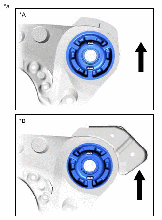
*A for Type A *B for Type B *a View from Underneath Front of the Vehicle Align a new front suspension member body mounting front cushion LH as shown in the illustration and set it to the front frame assembly.
Note
-
Position the front suspension member body mounting front cushion LH in the correct direction.
-
Do not apply lubricant to the outer sleeve of the front suspension member body mounting front cushion LH.
-
-
*1 Front Suspension Member Body Mounting Front Cushion LH Install SST as shown in the illustration.
- SST
- 09830-10010 ( 09830-01010, 09830-01020, 09830-01030, 09830-01060 )
Note
Be sure to install SST (09830-01030) in the correct direction.
-
*a Hold Turn Using SST, install the front suspension member body mounting front cushion LH as shown in the illustration.
Note
Check that there is no clearance between the front frame assembly and the front suspension member body mounting front cushion LH.
-
-
INSTALL FRONT SUSPENSION MEMBER BODY MOUNTING FRONT CUSHION
-
*a View from Underneath Front of the Vehicle Align a new front suspension member body mounting front cushion as shown in the illustration and set it to the front frame assembly.
Note
-
Position the front suspension member body mounting front cushion in the correct direction.
-
Do not apply lubricant to the outer sleeve of the front suspension member body mounting front cushion.
-
-
Install SST using the same procedure as for the front suspension member body mounting front cushion.
- SST
- 09830-10010 ( 09830-01010, 09830-01020, 09830-01030, 09830-01060 )
Note
Be sure to install SST (09830-01030) in the correct direction.
-
Using SST, install each front suspension member body mounting front cushion as shown in the illustration.
Note
Check that there is no clearance between the front frame assembly and the front suspension member body mounting front cushion.
Tech Tips
Perform the same procedure as for the front suspension member body mounting front cushion LH.
-
-
INSTALL FRONT SUSPENSION MEMBER BODY MOUNTING REAR STOPPER
-
Install the 2 front suspension member body mounting rear stoppers to the front frame assembly.
-
-
INSTALL FRONT SUSPENSION MEMBER BODY MOUNTING FRONT STOPPER
-
Install the 2 front suspension member body mounting front stoppers to the front frame assembly.
-
-
INSTALL FRONT NO. 2 SUSPENSION MEMBER DYNAMIC DAMPER (for 2GR-FKS 2WD)
-
Install the front No. 2 suspension member dynamic damper to the front frame assembly with the 2 bolts.
- Torque:
- 29 N*m { 296 kgf*cm, 21 ft.*lbf }
-
-
INSTALL FRONT SUSPENSION MEMBER DYNAMIC DAMPER (except 2GR-FKS AWD)
-
Install the front suspension member dynamic damper to the front frame assembly with the 3 bolts.
- Torque:
- 29 N*m { 296 kgf*cm, 21 ft.*lbf }
-
-
INSTALL FRONT SUSPENSION MEMBER DUMPER PLATE (except 2GR-FKS AWD)
-
Install the front suspension member damper plate to the front suspension member dynamic damper with the 2 nuts.
- Torque:
- 4.9 N*m { 50 kgf*cm, 43 in.*lbf }
-
-
INSTALL FRONT LOWER NO. 1 SUSPENSION ARM SUB-ASSEMBLY LH
-
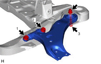
Install the front lower No. 1 suspension arm sub-assembly LH to the front frame assembly with the 3 bolts and nut in the order shown in the illustration.
- Torque:
- Bolt (1), (2)
- 200 N*m { 2039 kgf*cm, 148 ft.*lbf }
- Bolt (3)
- 135 N*m { 1377 kgf*cm, 100 ft.*lbf }
Note
Because the nut has its own stopper, do not turn the nut. Tighten the bolt with the nut secured.
-
-
INSTALL FRONT LOWER NO. 1 SUSPENSION ARM SUB-ASSEMBLY RH
Tech Tips
Perform the same procedure as for the LH side.
-
INSTALL FRONT ENGINE MOUNTING INSULATOR
for 2GR-FKS: Click here
for 8AR-FTS: Click here
-
INSTALL REAR ENGINE MOUNTING INSULATOR
for 2GR-FKS: Click here
for 8AR-FTS: Click here
-
INSTALL FRONT FRAME ASSEMBLY
for 2GR-FKS: Click here
for 8AR-FTS: Click here