AIR CONDITIONING SYSTEM(for Automatic Air Conditioning System) PTC Heater Circuit
| DTC Code | DTC Name |
|---|---|
| PTC Heater Circuit |
DESCRIPTION
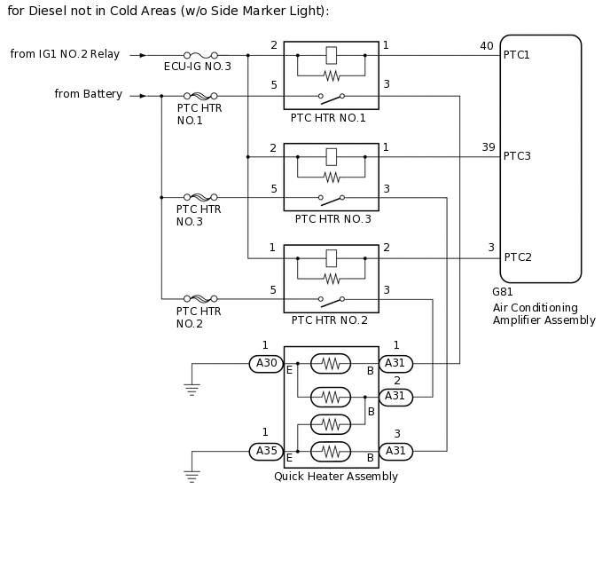
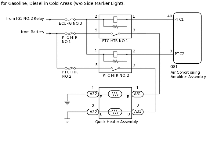
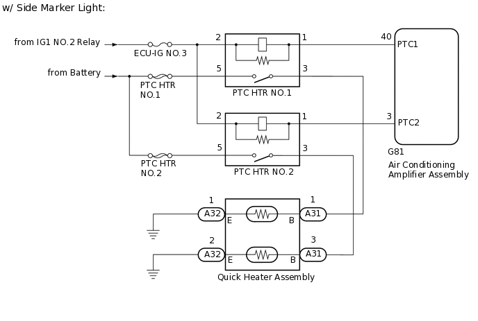
The air conditioning amplifier assembly sends operation signals to the PTC heater relays when quick heater assembly operation conditions are met. Based on the signals from the air conditioning amplifier assembly, the PTC heater relays turn on, and power is supplied to the quick heater assembly installed in the air conditioning radiator assembly.
Control ECU |
Condition |
|---|---|
Air Conditioning Amplifier Assembly |
Engine running |
Combination switch assembly (ECO mode switch) off |
|
Blower motor on |
|
Temperature set to MAX HOT |
|
IDH terminal signal below 1 V (Inverter with converter assembly overload not detected) |
|
|
|
Ambient temperature 10°C or less |
WIRING DIAGRAM
CAUTION / NOTICE / HINT
Inspect the fuses for circuits related to this system before performing the following procedure.
PROCEDURE
PERFORM ACTIVE TEST USING GTS
Connect the GTS to the DLC3.
Turn the ignition switch to ON.
Turn the GTS on.
Enter the following menus: Body Electrical / Air Conditioner / Active Test.
Check the operation by referring to the table below.
Body Electrical > Air Conditioner > Active Test
Tester Display
Measurement Item
Control Range
Diagnostic Note
Heater Active Level
Quick heater assembly
Min.: 0, Max.: 3
-
Body Electrical > Air Conditioner > Active Test
Tester Display
Heater Active Level
Result
Proceed to
Heater Active Level changes normally
Heater Active Level does not change normally
Heater Active Level does not change normally PROCEED TO NEXT SUSPECTED AREA SHOWN IN PROBLEM SYMPTOMS TABLE
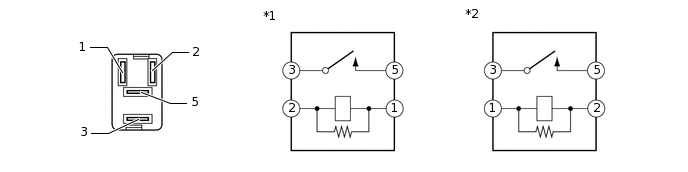
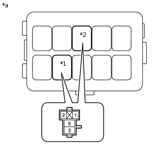
INSPECT PTC HEATER RELAY
for Diesel not in Cold Areas (w/o Side Marker Light):
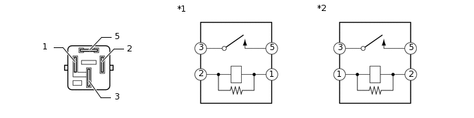
*1
PTC HTR NO.2 Relay
*2
PTC HTR NO.1 Relay, PTC HTR NO.3 Relay
Remove the PTC heater relays from the No. 2 engine room relay block.
Measure the resistance according to the value(s) in the table below.
Standard Resistance
Tester Connection
Condition
Specified Condition
3 - 5
Battery voltage is not applied between terminals 1 and 2
10 kΩ or higher
3 - 5
Battery voltage is applied between terminals 1 and 2
Below 1 Ω
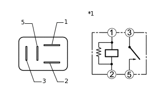
for Gasoline, Diesel in Cold Areas (w/o Side Marker Light):
*1
PTC HTR NO.2 Relay
*2
PTC HTR NO.1 Relay
Remove the PTC heater relays from the No. 2 engine room relay block.
Measure the resistance according to the value(s) in the table below.
Standard Resistance
Tester Connection
Condition
Specified Condition
3 - 5
Battery voltage is not applied between terminals 1 and 2
10 kΩ or higher
3 - 5
Battery voltage is applied between terminals 1 and 2
Below 1 Ω
-
*1
PTC HTR NO.2 Relay
PTC HTR NO.1 Relay
w/ Side Marker Light:
Remove the PTC heater relays from the No. 2 engine room relay block.
Measure the resistance according to the value(s) in the table below.
Standard Resistance
Tester Connection
Condition
Specified Condition
3 - 5
Battery voltage is not applied between terminals 1 and 2
10 kΩ or higher
3 - 5
Battery voltage is applied between terminals 1 and 2
Below 1 Ω
Result
Proceed to
OK
NG
NG REPLACE PTC HEATER RELAY
CHECK HARNESS AND CONNECTOR (PTC HEATER RELAY - BATTERY)
-
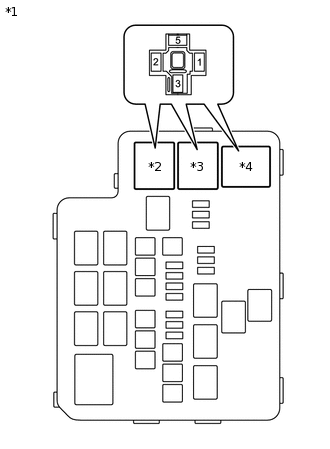
*1
No. 2 Engine Room Relay Block
*2
PTC HTR NO.1 Relay
*3
PTC HTR NO.2 Relay
*4
PTC HTR NO.3 Relay
for Diesel not in Cold Areas (w/o Side Marker Light):
Remove the PTC heater relays from the No. 2 engine room relay block.
Measure the voltage according to the value(s) in the table below.
Standard Voltage
PTC HTR NO.1
Tester Connection
Condition
Specified Condition
5 - Body ground
Always
11 to 14 V
2 - Body ground
Ignition switch off
Below 1 V
Ignition switch ON
11 to 14 V
PTC HTR NO.2
Tester Connection
Condition
Specified Condition
5 - Body ground
Always
11 to 14 V
1 - Body ground
Ignition switch off
Below 1 V
Ignition switch ON
11 to 14 V
PTC HTR NO.3
Tester Connection
Condition
Specified Condition
5 - Body ground
Always
11 to 14 V
2 - Body ground
Ignition switch off
Below 1 V
Ignition switch ON
11 to 14 V
-
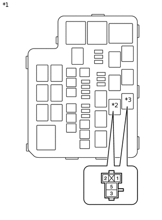
*1
No. 2 Engine Room Relay Block
*2
PTC HTR NO.1 Relay
*3
PTC HTR NO.2 Relay
for Gasoline, Diesel in Cold Areas (w/o Side Marker Light):
Remove the PTC heater relays from the No. 2 engine room relay block.
Measure the voltage according to the value(s) in the table below.
Standard Voltage
PTC HTR NO.1
Tester Connection
Condition
Specified Condition
5 - Body ground
Always
11 to 14 V
2 - Body ground
Ignition switch off
Below 1 V
Ignition switch ON
11 to 14 V
PTC HTR NO.2
Tester Connection
Condition
Specified Condition
5 - Body ground
Always
11 to 14 V
1 - Body ground
Ignition switch off
Below 1 V
Ignition switch ON
11 to 14 V
-
*1
PTC HTR NO.1 Relay
*2
PTC HTR NO.2 Relay
*a
Component without relay installed
(No. 2 Engine Room Relay Block)
w/ Side Marker Light:
Remove the PTC heater relays from the No. 2 engine room relay block.
Measure the voltage according to the value(s) in the table below.
Standard Voltage
PTC HTR NO.1
Tester Connection
Condition
Specified Condition
5 - Body ground
Always
11 to 14 V
2 - Body ground
Ignition switch off
Below 1 V
Ignition switch ON
11 to 14 V
PTC HTR NO.2
Tester Connection
Condition
Specified Condition
5 - Body ground
Always
11 to 14 V
2 - Body ground
Ignition switch off
Below 1 V
Ignition switch ON
11 to 14 V
Result
Proceed to
OK
NG
NG REPAIR OR REPLACE HARNESS OR CONNECTOR
-
CHECK HARNESS AND CONNECTOR (PTC HEATER RELAY - AIR CONDITIONING AMPLIFIER ASSEMBLY)
for Diesel not in Cold Areas (w/o Side Marker Light):
Disconnect the G81 air conditioning amplifier assembly connector.
Remove the PTC heater relays from the No. 2 engine room relay block.
Measure the resistance according to the value(s) in the table below.
Standard Resistance
Tester Connection
Condition
Specified Condition
1 - G81-40 (PTC1)
Always
Below 1 Ω
2 - G81-3 (PTC2)
Always
Below 1 Ω
1 - G81-39 (PTC3)
Always
Below 1 Ω
G81-40 (PTC1) - Body ground
Always
10 kΩ or higher
G81-3 (PTC2) - Body ground
Always
10 kΩ or higher
G81-39 (PTC3) - Body ground
Always
10 kΩ or higher
for Gasoline, Diesel in Cold Areas (w/o Side Marker Light):
Disconnect the G81 air conditioning amplifier assembly connector.
Remove the PTC heater relays from the No. 2 engine room relay block.
Measure the resistance according to the value(s) in the table below.
Standard Resistance
Tester Connection
Condition
Specified Condition
1 - G81-40 (PTC1)
Always
Below 1 Ω
2 - G81-3 (PTC2)
Always
Below 1 Ω
G81-40 (PTC1) - Body ground
Always
10 kΩ or higher
G81-3 (PTC2) - Body ground
Always
10 kΩ or higher
w/ Side Marker Light:
Disconnect the G81 air conditioning amplifier assembly connector.
Remove the PTC heater relays from the No. 2 engine room relay block.
Measure the resistance according to the value(s) in the table below.
Standard Resistance
Tester Connection
Condition
Specified Condition
1 - G81-40 (PTC1)
Always
Below 1 Ω
1 - G81-3 (PTC2)
Always
Below 1 Ω
G81-40 (PTC1) - Body ground
Always
10 kΩ or higher
G81-3 (PTC2) - Body ground
Always
10 kΩ or higher
Result
Proceed to
OK
NG
NG REPAIR OR REPLACE HARNESS OR CONNECTOR
CHECK HARNESS AND CONNECTOR (PTC HEATER RELAY - QUICK HEATER ASSEMBLY)
for Diesel not in Cold Areas (w/o Side Marker Light):
Remove the PTC heater relays from the No. 2 engine room relay block.
Disconnect the A31 quick heater assembly connector.
Measure the resistance according to the value(s) in the table below.
Standard Resistance
PTC HTR NO.1
Tester Connection
Condition
Specified Condition
3 - A31-1 (B)
Always
Below 1 Ω
A31-1 (B) - Body ground
Always
10 kΩ or higher
PTC HTR NO.2
Tester Connection
Condition
Specified Condition
3 - A31-2 (B)
Always
Below 1 Ω
A31-2 (B) - Body ground
Always
10 kΩ or higher
PTC HTR NO.3
Tester Connection
Condition
Specified Condition
3 - A31-3 (B)
Always
Below 1 Ω
A31-3 (B) - Body ground
Always
10 kΩ or higher
for Gasoline, Diesel in Cold Areas (w/o Side Marker Light):
Remove the PTC heater relays from the No. 2 engine room relay block.
Disconnect the A31 quick heater assembly connector.
Measure the resistance according to the value(s) in the table below.
Standard Resistance
PTC HTR NO.1
Tester Connection
Condition
Specified Condition
3 - A31-1 (B)
Always
Below 1 Ω
A31-1 (B) - Body ground
Always
10 kΩ or higher
PTC HTR NO.2
Tester Connection
Condition
Specified Condition
3 - A31-3 (B)
Always
Below 1 Ω
A31-3 (B) - Body ground
Always
10 kΩ or higher
w/ Side Marker Light:
Remove the PTC heater relays from the No. 2 engine room relay block.
Disconnect the A31 quick heater assembly connector.
Measure the resistance according to the value(s) in the table below.
Standard Resistance
PTC HTR NO.1
Tester Connection
Condition
Specified Condition
3 - A31-1 (B)
Always
Below 1 Ω
A31-1 (B) - Body ground
Always
10 kΩ or higher
PTC HTR NO.2
Tester Connection
Condition
Specified Condition
3 - A31-3 (B)
Always
Below 1 Ω
A31-3 (B) - Body ground
Always
10 kΩ or higher
Result
Proceed to
OK
NG
NG REPAIR OR REPLACE HARNESS OR CONNECTOR
CHECK HARNESS AND CONNECTOR (QUICK HEATER ASSEMBLY - BODY GROUND)
for Diesel not in Cold Areas (w/o Side Marker Light):
Disconnect the A30 and A35 quick heater assembly connectors.
Measure the resistance according to the value(s) in the table below.
Standard Resistance
Tester Connection
Condition
Specified Condition
A30-1 (E) - Body ground
Always
Below 1 Ω
A35-1 (E) - Body ground
Always
Below 1 Ω
for Gasoline, Diesel in Cold Areas (w/o Side Marker Light):
Disconnect the A32 quick heater assembly connector.
Measure the resistance according to the value(s) in the table below.
Standard Resistance
Tester Connection
Condition
Specified Condition
A32-1 (E) - Body ground
Always
Below 1 Ω
A32-2 (E) - Body ground
Always
Below 1 Ω
w/ Side Marker Light:
Disconnect the A32 quick heater assembly connector.
Measure the resistance according to the value(s) in the table below.
Standard Resistance
Tester Connection
Condition
Specified Condition
A32-1 (E) - Body ground
Always
Below 1 Ω
A32-2 (E) - Body ground
Always
Below 1 Ω
Result
Proceed to
OK
NG
NG REPAIR OR REPLACE HARNESS OR CONNECTOR
INSPECT QUICK HEATER ASSEMBLY
Remove the quick heater assembly.
Inspect the quick heater assembly.
Result
Proceed to
OK
NG