LIGHTING SYSTEM Door Courtesy Switch Circuit
| DTC Code | DTC Name |
|---|---|
| Door Courtesy Switch Circuit |
DESCRIPTION
The main body ECU receives a door open/closed signal from each door courtesy light switch.
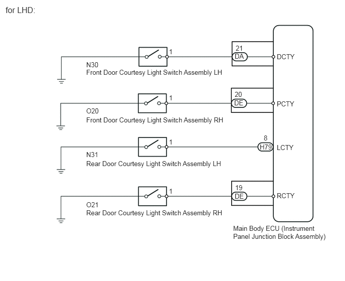
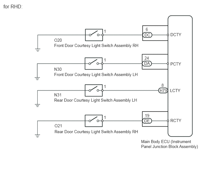
WIRING DIAGRAM
PROCEDURE
READ VALUE USING INTELLIGENT TESTER (DOOR COURTESY LIGHT SWITCH)
Connect the intelligent tester to the DLC3.
Turn the ignition switch to ON.
Turn the intelligent tester on.
Enter the following menus: Body / Main Body / Data List.
According to the display on the intelligent tester, read the Data List.
Table 1. Main Body Tester Display
Measurement Item/Range
Normal Condition
Diagnostic Note
D Door Courtesy SW
Driver side door courtesy light switch signal / ON or OFF
ON: Driver side door courtesy light switch on
OFF: Driver side door courtesy light switch off
-
P Door Courtesy SW
Front passenger side door courtesy light switch signal / ON or OFF
ON: Front passenger side door courtesy light switch on
OFF: Front passenger side door courtesy light switch off
-
RL Door Courtesy SW
Rear door courtesy light switch LH signal / ON or OFF
ON: Rear door courtesy light switch LH on
OFF: Rear door courtesy light switch LH off
-
RR Door Courtesy SW
Rear door courtesy light switch RH signal / ON or OFF
ON: Rear door courtesy light switch RH on
OFF: Rear door courtesy light switch RH off
-
Table 2. Result Result
Proceed to
OK
A
NG (Front door courtesy light switch LH does not operate)
B
NG (Front door courtesy light switch RH does not operate)
C
NG (Rear door courtesy light switch LH does not operate)
D
NG (Rear door courtesy light switch RH does not operate)
E
INSPECT FRONT DOOR COURTESY LIGHT SWITCH ASSEMBLY RHClick here
INSPECT REAR DOOR COURTESY LIGHT SWITCH ASSEMBLY LHClick here
INSPECT REAR DOOR COURTESY LIGHT SWITCH ASSEMBLY RHClick here
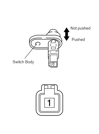
INSPECT FRONT DOOR COURTESY LIGHT SWITCH ASSEMBLY LH
-
Remove the front door courtesy light switch LH (Click here).
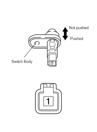
Measure the resistance according to the value(s) in the table below.
Standard Resistance
Tester Connection
Switch Condition
Specified Condition
1 - Switch body
Not pushed
Below 1 Ω
Pushed
10 kΩ or higher
-
CHECK HARNESS AND CONNECTOR (FRONT DOOR COURTESY LIGHT SWITCH LH - MAIN BODY ECU)
-
Disconnect the N30 front door courtesy light switch LH connector.
Disconnect the DA main body ECU connector.
Measure the resistance according to the value(s) in the table below.
Standard Resistance
for LHD
Tester Connection
Condition
Specified Condition
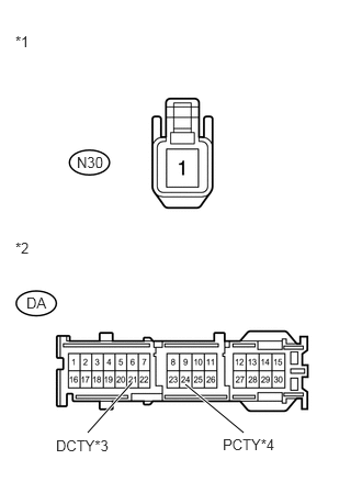
N30-1 - DA-21 (DCTY)
Always
Below 1 Ω
N30-1 - Body ground
Always
10 kΩ or higher
for RHD
Tester Connection
Condition
Specified Condition
N30-1 - DA-24 (PCTY)
Always
Below 1 Ω
N30-1 - Body ground
Always
10 kΩ or higher
Table 3. Text in Illustration *1
Front view of wire harness connector
(to Front Door Courtesy Light Switch LH)
*2
Front view of wire harness connector
(to Main Body ECU)
*3
for LHD
*4
for RHD
REPLACE MAIN BODY ECU (INSTRUMENT PANEL JUNCTION BLOCK ASSEMBLY)
REPAIR OR REPLACE HARNESS OR CONNECTOR
-
INSPECT FRONT DOOR COURTESY LIGHT SWITCH ASSEMBLY RH
-
Remove the front door courtesy light switch RH (Click here).
Measure the resistance according to the value(s) in the table below.
Standard Resistance
Tester Connection
Switch Condition
Specified Condition
1 - Switch body
Not pushed
Below 1 Ω
Pushed
10 kΩ or higher
-
CHECK HARNESS AND CONNECTOR (FRONT DOOR COURTESY LIGHT SWITCH RH - MAIN BODY ECU)
-
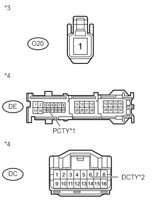
Disconnect the O20 front door courtesy light switch RH connector.
Disconnect the DE*1 or DC*2 main body ECU connector.
*1: for LHD
*2: for RHD
Measure the resistance according to the value(s) in the table below.
Standard Resistance
for LHD
Tester Connection
Condition
Specified Condition
O20-1 - DE-20 (PCTY)
Always
Below 1 Ω
O20-1 - Body ground
Always
10 kΩ or higher
for RHD
Tester Connection
Condition
Specified Condition
O20-1 - DC-6 (DCTY)
Always
Below 1 Ω
O20-1 - Body ground
Always
10 kΩ or higher
Table 4. Text in Illustration *1
for LHD
*2
for RHD
*3
Front view of wire harness connector
(to Front Door Courtesy Light Switch RH)
*4
Front view of wire harness connector
(to Main Body ECU)
REPLACE MAIN BODY ECU (INSTRUMENT PANEL JUNCTION BLOCK ASSEMBLY)
REPAIR OR REPLACE HARNESS OR CONNECTOR
-
INSPECT REAR DOOR COURTESY LIGHT SWITCH ASSEMBLY LH
-

Remove the rear door courtesy light switch LH (Click here).
Measure the resistance according to the value(s) in the table below.
Standard Resistance
Tester Connection
Switch Condition
Specified Condition
1 - Switch body
Not pushed
Below 1 Ω
Pushed
10 kΩ or higher
-
CHECK HARNESS AND CONNECTOR (REAR DOOR COURTESY LIGHT SWITCH LH - MAIN BODY ECU)
-
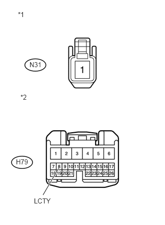
Disconnect the N31 rear door courtesy light switch LH connector.
Disconnect the H79 main body ECU connector.
Measure the resistance according to the value(s) in the table below.
Standard Resistance
Tester Connection
Condition
Specified Condition
N31-1 - H79-8 (LCTY)
Always
Below 1 Ω
N31-1 - Body ground
Always
10 kΩ or higher
Table 5. Text in Illustration *1
Front view of wire harness connector
(to Rear Door Courtesy Light Switch LH)
*2
Front view of wire harness connector
(to Main Body ECU)
REPLACE MAIN BODY ECU (INSTRUMENT PANEL JUNCTION BLOCK ASSEMBLY)
REPAIR OR REPLACE HARNESS OR CONNECTOR
-
INSPECT REAR DOOR COURTESY LIGHT SWITCH ASSEMBLY RH
-

Remove the rear door courtesy light switch RH (Click here).
Measure the resistance according to the value(s) in the table below.
Standard Resistance
Tester Connection
Switch Condition
Specified Condition
1 - Switch body
Not pushed
Below 1 Ω
Pushed
10 kΩ or higher
-
CHECK HARNESS AND CONNECTOR (REAR DOOR COURTESY LIGHT SWITCH RH - MAIN BODY ECU)
-
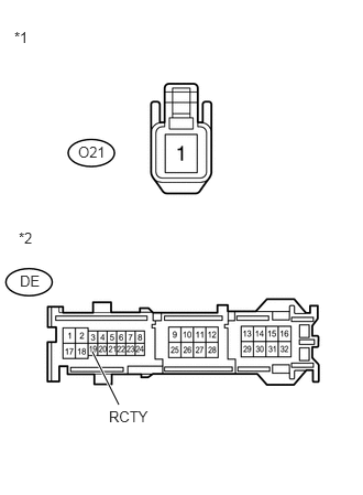
Disconnect the O21 rear door courtesy light switch RH connector.
Disconnect the DE main body ECU connector.
Measure the resistance according to the value(s) in the table below.
Standard Resistance
Tester Connection
Condition
Specified Condition
O21-1 - DE-19 (RCTY)
Always
Below 1 Ω
O21-1 - Body ground
Always
10 kΩ or higher
Table 6. Text in Illustration *1
Front view of wire harness connector
(to Rear Door Courtesy Light Switch RH)
*2
Front view of wire harness connector
(to Main Body ECU)
REPLACE MAIN BODY ECU (INSTRUMENT PANEL JUNCTION BLOCK ASSEMBLY)
REPAIR OR REPLACE HARNESS OR CONNECTOR
-