SFI SYSTEM, Diagnostic DTC:P0171, P0172, P1170, P117B
| DTC Code | DTC Name |
|---|---|
| P0171 | System Too Lean (Bank 1) |
| P0172 | System Too Rich (Bank 1) |
| P1170 | Port Injector Fuel Performance |
| P117B | Direct Injector Fuel Performance |
DESCRIPTION
The fuel trim is related to the feedback compensation value, not to the basic injection time. The fuel trim consists of both the short-term and the long-term fuel trim.
The short-term fuel trim is fuel compensation that is used to constantly maintain the air fuel ratio at stoichiometric levels. The signal from the air fuel ratio sensor indicates whether the air fuel ratio is rich or lean compared to the stoichiometric ratio. This triggers a reduction in the fuel injection volume if the air fuel ratio is rich and an increase in the fuel injection volume if it is lean.
Factors such as individual engine differences, wear over time and changes in operating environment cause short-term fuel trim to vary from the ideal theoretical value. The long-term fuel trim controls overall fuel compensation. The long-term fuel trim compensates for long term deviations of the fuel trim from the ideal theoretical value. These long term deviations result from the corrections made by the short-term fuel trim.
If both the short-term fuel and long-term fuel trim are lean or rich beyond predetermined values, it is interpreted as a malfunction, the ECM illuminates the MIL and sets a DTC.
| DTC No. | DTC Detection Condition | Trouble Area |
|---|---|---|
| P0171 | With warm engine and stable air fuel ratio feedback, fuel trim considerably in error to lean side. (2 trip detection logic) |
|
| P0172 | With warm engine and stable air fuel ratio feedback, fuel trim considerably in error to rich side. (2 trip detection logic) |
|
| P1170 | Although a DTC is stored for a rich or lean condition, the amount of fuel trim during direct injection is normal for 9 seconds. (1 trip detection logic) |
|
| P117B | Although a DTC is stored for a rich or lean condition, the amount of fuel trim during port injection is normal for 9 seconds. (1 trip detection logic) |
|
Tech Tips
-
When DTC P0171 is set, the actual air-fuel ratio is on the lean side. When DTC P0172 is set, the actual air-fuel ratio is on the rich side.
-
If the vehicle runs out of fuel, the air-fuel ratio is lean and DTC P0171 may be set. The MIL is then illuminated.
-
When DTC P1170 or P117B is output , it may not be possible to precisely determine whether the port injection or the direct injection is malfunctioning, depending on the conditions. In this case, perform an Active Test (control the injection way) to determine which injection system is malfunctioning.
MONITOR DESCRIPTION
Under closed loop fuel control, fuel injection volumes that deviate from those estimated by the ECM cause changes in the long-term fuel trim compensation value. The long-term fuel trim is adjusted when there are persistent deviations in the short-term fuel trim values. Deviations from the ECM's estimated fuel injection volumes also affect the average fuel trim learning value, which is a combination of the average short-term fuel trim (fuel feedback compensation value) and the average long-term fuel trim (learning value of the air fuel ratio). If the average fuel trim learning value exceeds the malfunction threshold, the ECM interprets this as a malfunction in the fuel system and sets a DTC.
CONFIRMATION DRIVING PATTERN
-
Connect the GTS to the DLC3.
-
Turn the ignition switch to ON and turn the GTS on.
-
Clear DTCs (even if no DTCs are stored, perform the clear DTC operation) Click here.
-
Turn the ignition switch off and wait for at least 30 seconds.
-
Turn the ignition switch to ON and turn the GTS on.
-
Start the engine and warm it up until the engine coolant temperature reaches 75°C (167°F) or higher.
Tech Tips
Check the engine coolant temperature is 20°C (68°F) or less at engine started.
-
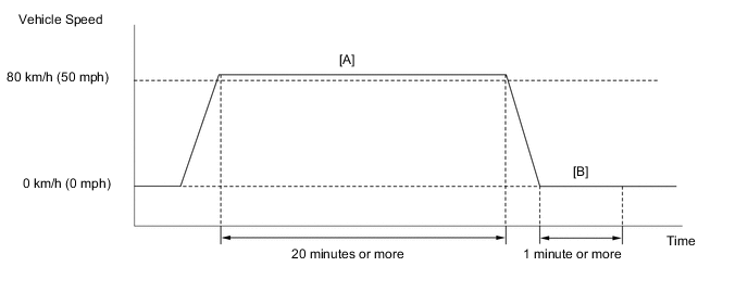
Perform the following the confirmation driving pattern.
CAUTION:
When performing the confirmation driving pattern, obey all speed limits and traffic laws.
-
Drive the vehicle at 80 km/h (50 mph) or more for 20 minutes or more [A].
-
Stop the vehicle.
-
Idle the engine for 1 minute or more [B].
-
Enter the following menus: Powertrain / Engine / Trouble Codes.
-
Read pending DTCs.
Tech Tips
-
If a pending DTC is output, the system is malfunctioning.
-
If a pending DTC is not output, perform the following procedure.
-
-
Enter the following menus: Powertrain / Engine / Utility / All Readiness.
-
Input the DTC: P0171, P0172, P1170 or P117B.
-
Check the DTC judgment result.
GTS Display Description NORMAL
-
DTC judgment completed
-
System normal
ABNORMAL
-
DTC judgment completed
-
System abnormal
INCOMPLETE
-
DTC judgment not completed
-
Perform driving pattern after confirming DTC enabling conditions
N/A
-
Unable to perform DTC judgment
-
Number of DTCs which do not fulfill DTC preconditions has reached ECU memory limit
Tech Tips
-
If the judgment result shows NORMAL, the system is normal.
-
If the judgment result shows ABNORMAL, the system has a malfunction.
-
-
If the test result is INCOMPLETE or N/A and no DTC is output, perform a universal trip and check for permanent DTCs Click here.
Tech Tips
-
If a permanent DTC is output, the system is malfunctioning.
-
If no permanent DTC is output, the system is normal.
-
CAUTION / NOTICE / HINT
Tech Tips
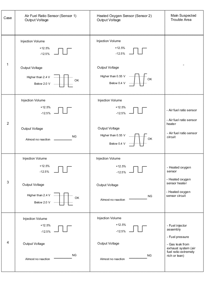
Malfunctioning areas can be identified by performing the Control the Injection Volume for A/F Sensor function provided in the Active Test. The Control the Injection Volume for A/F Sensor function can help to determine whether the air fuel ratio sensor, heated oxygen sensor and other potential trouble areas are malfunctioning.
The following instructions describe how to conduct the Control the Injection Volume for A/F Sensor operation using the GTS.
-
Connect the GTS to the DLC3.
-
Start the engine.
-
Turn the GTS on.
-
Warm up the engine at an engine speed of 2500 rpm for approximately 90 seconds.
-
Enter the following menus: Powertrain / Engine / Active Test / Control the Injection Volume for A/F Sensor / Gas AF Control / AFS Voltage B1S1 and O2S B1S2.
-
Perform the Active Test operation with the engine idling (press the RIGHT or LEFT button to change the fuel injection volume).
-
Monitor the output voltages of the air fuel ratio and heated oxygen sensors (AFS Voltage B1S1 and O2S B1S2) displayed on the GTS.
Tech Tips
-
Change the fuel injection volume within the range of -12.5% to +12.5%.
-
Each sensor reacts in accordance with increases and decreases in the fuel injection volume.
| GTS Display (Sensor) | Injection Volume | Status | Voltage |
|---|---|---|---|
| AFS Voltage B1S1 (Air fuel ratio) |
+12.5% | Rich | Below 2.0 V |
| -12.5% | Lean | Higher than 2.4 V | |
| O2S B1S2 (Heated oxygen) |
+12.5% | Rich | Higher than 0.55 V |
| -12.5% | Lean | Below 0.4 V |
Note
The air fuel ratio sensor has an output delay of a few seconds and the heated oxygen sensor has a maximum output delay of approximately 20 seconds.
-
Following the Control the Injection Volume for A/F Sensor procedure enables technicians to check and graph the voltage outputs of both the air fuel ratio and heated oxygen sensors.
-
To display the graph, enter the following menus: Powertrain / Engine / Active Test / Control the Injection Volume for A/F Sensor / Gas AF Control / AFS Voltage B1S1 and O2S B1S2; and then press the graph button on the Data List view.
Tech Tips
-
Bank 1 refers to the bank that includes the No. 1 cylinder*.
*: The No. 1 cylinder is the cylinder which is farthest from transmission.
-
Bank 2 refers to the bank that does not include the No. 1 cylinder.
-
Sensor 1 refers to the sensor closest to the engine assembly.
-
Sensor 2 refers to the sensor farthest away from the engine assembly.
-
Read freeze frame data using the GTS. The ECM records vehicle and driving condition information as freeze frame data the moment a DTC is stored. When troubleshooting, freeze frame data can be helpful in determining whether the vehicle was moving or stationary, whether the engine was warmed up or not, whether the air fuel ratio was lean or rich, as well as other data recorded at the time of a malfunction.
-
A low air fuel ratio sensor voltage could be caused by a rich air fuel mixture. Check for conditions that would cause the engine to run rich.
-
A high air fuel ratio sensor voltage could be caused by a lean air fuel mixture. Check for conditions that would cause the engine to run lean.
PROCEDURE
-
CHECK ANY OTHER DTCS OUTPUT (IN ADDITION TO DTC P0171, P0172, P1170 AND/OR P117B)
-
Connect the GTS to the DLC3.
-
Turn the ignition switch to ON.
-
Turn the GTS on.
-
Enter the following menus: Powertrain / Engine / Trouble Codes.
-
Read the DTCs.
Result Result Proceed to P0171, P0172, P1170 or P117B A P0171, P0172, P1170 and/or P117B and other DTCs B Tech Tips
If any DTCs other than P0171, P0172, P1170 or P117B are output, troubleshoot those DTCs first.
B 
GO TO DTC CHART Click here
A 
-
-
PERFORM ACTIVE TEST USING GTS (CONTROL THE INJECTION VOLUME FOR A/F SENSOR)
-
Connect the GTS to the DLC3.
-
Turn the ignition switch to ON.
-
Turn GTS on.
-
Warm up the engine and run the engine at an engine speed of 2500 rpm for approximately 90 seconds.
-
Enter the following menus: Powertrain / Engine / Active Test / Control the Injection Volume for A/F Sensor / AFS Voltage B1S1 and O2S B1S2.
-
Perform the Control the Injection Volume for A/F Sensor operation with the engine in an idling.
-
Monitor the output voltages of the A/F and HO2 sensors (AFS Voltage B1S1 and O2S B1S2) displayed on the GTS.
Tech Tips
-
Change the fuel injection volume within the range of -12.5% to 12.5%.
-
The air fuel ratio sensor has an output delay of a few seconds and the heated oxygen sensor has a maximum output delay of approximately 20 seconds.
-
If the sensor output voltage does not change (almost no reaction) while performing the Active Test, the sensor may be malfunctioning.
GTS Display (Sensor) Injection Volume Status Voltage AFS Voltage B1S1
(A/F)
12.5% Rich Less than 2.0 V -12.5% Lean More than 2.4 V O2S B1S2
(HO2)
12.5% Rich More than 0.55 V -12.5% Lean Less than 0.4 V Result Status
AFS Voltage B1S1
Status
O2S B1S2
A/F Condition and
A/F Sensor Condition
Suspected Trouble Area Proceed to Lean/Rich Lean/Rich Normal - A Lean Lean Actual air-fuel ratio lean
-
Ventilation valve and hose
-
Ventilation hose connections
-
Injector for port injection
-
Gas leakage from exhaust system
-
Air induction system
-
Fuel pressure
-
Mass Air Flow (MAF) meter
-
Engine Coolant Temperature (ECT) sensor
A Rich Rich Actual air-fuel ratio rich
-
Gas leakage from exhaust system
-
Ignition system
-
Fuel pressure
-
Mass air flow (MAF) meter
-
Engine coolant temperature (ECT) sensor
A Lean Lean/Rich A/F sensor malfunction
-
Air fuel ratio sensor
B Rich Lean/Rich A/F sensor malfunction
-
Air fuel ratio sensor
B Lean: During the Control the Injection Volume for A/F Sensor Active Test, the air fuel ratio sensor output voltage (AFS Voltage) is consistently higher than 2.4 V, and the heated oxygen sensor output voltage (O2S) is consistently below 0.4 V.
Rich: During the Control the Injection Volume for A/F Sensor Active Test, the AFS Voltage is consistently below 2.0 V, and the O2S is consistently higher than 0.55 V.
Lean/Rich: During the Control the Injection Volume for A/F Sensor Active Test, the output voltage of the heated oxygen sensor alternates correctly.
Tech Tips
Refer to "Data List / Active Test" [AFS Voltage B1S1 and O2S B1S2] Click here.
-
B 
INSPECT AIR FUEL RATIO SENSOR Click here
A
-
-
CHECK FREEZE FRAME DATA
-
Check freeze frame data, and understand the status of vehicles when abnormalities occur.
Tech Tips
-
The 5 separate sets of freeze frame data can be used to check the engine status before and after storing of the DTC.
-
Use freeze frame data to check if the engine was idling or running.
FREEZE FRAME DATA Engine Speed Fuel System Status #1 O2S B1S2 Calculate Load Short FT #1 Evap Purge Flow Vehicle Speed Long FT #1 Shift Position Sig from ECT MAF AFS Voltage B1S1 Coolant Temp -
NEXT
-
-
CHECK VEHICLE CONDITION
Tech Tips
When checking trouble during abnormal status, use the following procedure.
-
Remove the EFI (+B) fuse, wait 60 seconds or more, and connect the fuse.
Tech Tips
-
Clear the ECM feedback learning value.
-
After clearing the DTC, initial diagnosis of the electronically controlled throttle is performed. Accordingly, engine start after clearing DTC takes place 10 seconds or more after turning the ignition switch ON.
-
-
Connect the GTS to the DLC3.
-
Turn the ignition switch to ON.
-
Turn GTS on.
-
Enter the following menus: Powertrain / Engine / Active Test / Control the Injection Volume.
-
Increase or decrease injection quantities by 1 step.
Tech Tips
This operation stops feedback compensation and feedback learning, enabling checking of trouble.
-
Start the engine.
-
Refer to the running state freeze frame data, reproduce the conditions in which the abnormality occurred, and check the trouble.
Result Result Proceed to Trouble can be confirmed. A Trouble cannot be confirmed. B
B
READ VALUE USING GTS (SHORT FT #1 AND LONG FT #1) Click here
A
-
-
CHECK VEHICLE CONDITION
-
Specify the location of the trouble from the following, then conduct inspections and replacements.
Note
If only the check light is lit, and it is not possible to specify the location of the trouble, then go to step 3.
Trouble area Symptom Cause Troubleshooting Diagnostic note Mass air flow meter
-
Rough idling
-
Pausing at start-up
-
MIL lights up only.
Deviation in characteristic of the mass air flow meter Refer to Click here.
- Fuel injector assembly (for port injection or direct injection) MIL lights up only. Fuel injector assembly blockage
-
Refer to Click here for port injection.
-
Refer to Click here for direct injection.
-
Very long unattended idle time
-
Long running distance
-
Long-term usage of regular gasoline
From the vehicle usage conditions above, there may be a blockage in the fuel injector assembly.
During driving, the MIL lights up often.
-
Engine stalls when the vehicle stops (restart is possible).
-
MIL lights up only.
Problem with oil-tightness in fuel injector assembly
-
Refer to Click here for port injection.
-
Refer to Click here for direct injection.
-
Problem with oil-tightness results in a rich side abnormality
-
If a high concentration of HC within the intake manifold after the engine stopped, this results in a rich side abnormality.
-
From scorching on the spark plug, there may be a fuel system abnormality.
-
DTC P0088 may have been stored.
Fuel pump assembly
-
Engine stall
-
Poor acceleration
-
Fuel pump assembly malfunction
-
Low pressure side fuel pressure abnormality
-
Low pressure side fuel system blockage
-
Refer to Click here for fuel pump control circuit (low pressure side).
-
Refer to Click here for fuel pressure (low pressure side).
- Intake system
-
Rough idling
-
MIL lights up only.
Air sucked in from the intake manifold gasket. Check intake manifold gasket inspection. -
-
Damage to intake system hoses
-
Continuous the purge valve stuck on
Start the engine, and in idle condition block off individual hoses connected to the intake manifold, and check that the fuel compensation quantity (total of feedback compensated value and feedback learning value) decreases. If air is being drawn into the hose, the fuel compensation quantity (total of feedback compensated value and feedback learning value) is large, and this drops with a racing condition. Air fuel ratio sensor Rough idling Air fuel ratio sensor malfunction Refer to Click here.
Air fuel ratio sensor system DTC may be stored. -
-
After the trouble area is repaired, Check that the trouble symptom is resolved.
Result Result Proceed to Trouble symptom resolved A Trouble symptom not resolved B
B
READ VALUE USING GTS (SHORT FT #1 AND LONG FT #1) Click here
A
-
-
CLEAR DTC
-
Connect the GTS to the DLC3.
-
Turn the ignition switch to ON.
-
Turn the GTS on.
-
Clear the DTCs Click here.
NEXT
-
-
READ VALUE USING GTS (SHORT FT #1 AND LONG FT #1)
-
Connect the GTS to the DLC3.
-
Turn the ignition switch to ON.
-
Turn the GTS on.
-
Start the engine.
-
Enter the following menus: Powertrain / Engine / Data List / Short #1, Long FT #1.
-
Read the value Short #1 and Long FT #1.
Result GTS display Condition Specified condition Short FT #1 + Long FT #1 Vehicle condition when the malfunction occurs (Idling or driving) -20% to +20% Tech Tips
If the trouble occurs during high speed driving, it is possible to take measurements at medium or low speeds by matching the intake air volume to that at the time of the trouble by shifting down.
NG
READ VALUE USING GTS (SHORT FT #1 AND LONG FT #1) Click here
OK
-
-
CHECK VEHICLE CONDITION
-
Check the diagnostic table and freeze frame data again, and if there is no abnormality, finish operations.
Tech Tips
-
In the event of running out of gas, the fuel compensation quantity will increase by +35% or more, and if this continues for 2 trips, this is a lean abnormality, and P0171 may be stored.
-
Repeated short trips (a short time between the ignition switch ON and turning it off or short distance driving) result in gasoline vaporizing at subsequent engine warm-up, and P0172 as a result of increased blow-by gas may be stored.
-
NEXT
END
-
-
READ VALUE USING GTS (SHORT FT #1 AND LONG FT #1)
-
Connect the GTS to the DLC3.
-
Start the engine.
-
Turn the GTS on.
-
Enter the following menus: Powertrain / Engine / Active Test / Control the Injection Way / Port.
-
Read the value Short FT #1 and Long FT #1.
Standard GTS display Condition Specified condition Short FT #1 + Long FT #1 Idling -20% to +20% -
Enter the following menus: Powertrain / Engine / Active Test / Control the Injection Way / Direct.
-
Read the value Short FT #1 and Long FT #1.
Standard GTS display Condition Specified condition Short FT #1 + Long FT #1 Idling -20% to +20% Result Control the Injection Way Proceed to Port Direct OK OK A OK NG B NG OK C NG NG D
B
READ VALUE USING GTS (FUEL PRESS) Click here
C
INSPECT FUEL INJECTOR ASSEMBLY (FOR PORT INJECTION) Click here
D
CHECK EMISSION CONTROL SYSTEM Click here
A
-
-
CHECK VEHICLE CONDITION
-
Check the diagnostic table and freeze frame data again, and if there is no abnormality, finish operations.
Tech Tips
-
In the event of running out of gas, the fuel compensation quantity will increase by +35% or more, and if this continues for 2 trips, this is a lean abnormality, and P0171 may be stored.
-
Repeated short trips (a short time between turning the ignition switch ON and turning it off or short distance driving) result in gasoline vaporizing at subsequent engine warm-up, and P0172 as a result of increased blow-by gas may be stored.
-
NEXT
END
-
-
CHECK EMISSION CONTROL SYSTEM
-
Check emission control system Click here.
NG
REPAIR OR REPLACE EMISSION CONTROL SYSTEM
OK
-
-
CHECK INTAKE SYSTEM
-
Check the intake system for vacuum leaks Click here.
OK No leaks in intake system.
NG
REPAIR OR REPLACE INTAKE SYSTEM
OK
-
-
INSPECT ENGINE COOLANT TEMPERATURE SENSOR
-
Inspect the engine coolant temperature sensor Click here.
NG
REPLACE ENGINE COOLANT TEMPERATURE SENSOR Click here
OK
-
-
READ VALUE USING GTS (MAF)
-
Connect the GTS to the DLC3.
-
Turn the ignition switch to ON.
-
Turn the GTS on.
-
Start the engine.
-
Enter the following menus: Powertrain / Engine / Data List / MAF.
-
Read MAF with the engine speed at 3000 rpm.
Standard GTS display Condition Specified condition MAF Engine speed at 3000 rpm 8 to 13 g/s
NG
CHECK HARNESS AND CONNECTOR (MASS AIR FLOW METER CONNECTOR CONNECTION) Click here
OK
-
-
CHECK IGNITION SYSTEM
-
Check the ignition system Click here.
NG
REPAIR OR REPLACE IGNITION SYSTEM
OK
-
-
CHECK FOR EXHAUST GAS LEAK
-
Check for exhaust gas leaks.
OK No gas leaks. Result Result Proceed to Abnormal A Normal B
A
REPAIR OR REPLACE EXHAUST SYSTEM
B
CHECK HARNESS AND CONNECTOR (MASS AIR FLOW METER CONNECTOR CONNECTION) Click here
-
-
INSPECT AIR FUEL RATIO SENSOR
-
Inspect the air fuel ratio sensor Click here.
NG
REPLACE AIR FUEL RATIO SENSOR Click here
OK
-
-
CHECK HARNESS AND CONNECTOR (AIR FUEL RATIO SENSOR - ECM)
-
Disconnect the air fuel ratio sensor connector.
-
Disconnect the ECM connector.
-
Measure the resistance according to the value(s) in the table below.
Standard Resistance (Check for open) Tester Connection Condition Specified Condition A34-19 (A1A+) - C14-3 (A1A+) Always Below 1 Ω A34-18 (A1A-) - C14-4 (A1A-) Always Below 1 Ω A34-5 (HA1A) - C14-1 (HA1A) Always Below 1 Ω Standard Resistance (Check for short) Tester Connection Condition Specified Condition A34-19 (A1A+) or C14-3 (A1A+) - Body ground Always 10 kΩ or higher A34-18 (A1A-) or C14-4 (A1A-) - Body ground Always 10 kΩ or higher A34-5 (HA1A) or C14-1 (HA1A) - Body ground Always 10 kΩ or higher
NG
REPAIR OR REPLACE HARNESS OR CONNECTOR
OK
-
-
REPLACE AIR FUEL RATIO SENSOR
-
Replace the air fuel ratio sensor Click here.
NEXT
-
-
READ VALUE USING GTS (SHORT FT #1 AND LONG FT #1)
-
Connect the GTS to the DLC3.
-
Turn the ignition switch to ON.
-
Turn the GTS on.
-
Start the engine.
-
Enter the following menus: Powertrain / Engine / Data List / Short FT #1, Long FT #1.
-
Read the value displayed on the GTS.
Standard GTS display Condition Specified condition Short FT #1 + Long FT #1 Idling or racing -20% to +20% Tech Tips
If the trouble occurs during high speed driving, it is possible to take measurements at medium or low speeds by matching the intake air volume to that at the time of the trouble by shifting down.
OK
END
NG
-
-
CHECK FUEL PRESSURE (LOW PRESSURE SIDE)
-
Check the fuel pressure (low pressure side) Click here.
Result Result Proceed to Abnormal A Normal B
A
REPAIR OR REPLACE FUEL SYSTEM (LOW PRESSURE SIDE)
B
CHECK HARNESS AND CONNECTOR (MASS AIR FLOW METER CONNECTOR CONNECTION) Click here
-
-
READ VALUE USING GTS (FUEL PRESS)
-
Connect the GTS to the DLC3.
-
Turn the ignition switch to ON.
-
Turn the GTS on.
-
Start the engine.
-
Enter the following menus: Powertrain / Engine / Data List / Fuel Press.
-
Read the value displayed on the GTS.
Standard GTS display Condition Specified condition Fuel Press Idling 3000 to 5000 kPa (30.6 to 50.9 kgf/cm2, 436 to 725 psi)
Tech Tips
-
The A/C switch and all accessory switches should be off, and the shift lever should be in the N, P or neutral, and the engine should be fully warmed up.
-
If the result is other than the standard value, there may be a fuel system (high pressure side) abnormality.
-
NG
REPAIR OR REPLACE FUEL SYSTEM (HIGH PRESSURE SIDE)
OK
-
-
PERFORM ACTIVE TEST USING GTS (CONTROL THE INJECTION WAY)
-
Connect the GTS to the DLC3.
-
Start the engine.
-
Turn the GTS on.
-
Enter the following menus: Powertrain / Engine / Active Test / Control the Injection Way / Direct.
-
Read the value Fuel Press Target Value, Short FT #1 and Long FT #1.
Standard GTS display Condition Proceed to Fuel Pressure Target Value Short FT #1 + Long FT #1 3 to 5 MPa (30.6 to 50.9 kgf/cm2, 436 to 725 psi)
- Idling A 5 MPa (50.9 kgf/cm2, 725 psi) or more
+20% or more B 5 MPa (50.9 kgf/cm2, 725 psi) or more
-20% or less C 3 MPa (30.6 kgf/cm2, 436 psi) or less
+20% or more C 3 MPa (30.6 kgf/cm2, 436 psi) or less
-20% or less D Tech Tips
The A/C switch and all accessory switches should be off, and the shift lever should be in the N, P or neutral, and the engine should be fully warmed up.
B
READ VALUE USING GTS (FUEL PRESS) Click here
C
REPLACE FUEL PRESSURE SENSOR Click here
D
REPLACE FUEL INJECTOR ASSEMBLY (FOR DIRECT INJECTION) Click here
A
-
-
PERFORM ACTIVE TEST USING GTS (CONTROL THE INJECTION WAY)
-
Connect the GTS to the DLC3.
-
Start the engine.
-
Turn the GTS on.
-
Enter the following menus: Powertrain / Engine / Active Test / Control the Injection Way / Direct.
-
Read the value Fuel Press Target Value, Short FT #1 and Long FT #1.
Standard GTS display Condition Proceed to Fuel Pressure Target Value Short FT #1 + Long FT #1 3 to 5 MPa (30.6 to 50.9 kgf/cm2, 436 to 725 psi)
-25% or less Idling A 3 to 5 MPa (30.6 to 50.9 kgf/cm2, 436 to 725 psi)
+30% or more 5 MPa (50.9 kgf/cm2, 725 psi) or more
-25% to 25% B Tech Tips
The A/C switch and all accessory switches should be off, and the shift lever should be in the N, P or neutral, and the engine should be fully warmed up.
A
REPLACE ECM Click here
B
CHECK FOR INTERMITTENT PROBLEMS Click here
-
-
READ VALUE USING GTS (FUEL PRESS)
-
Connect the GTS to the DLC3.
-
Turn the ignition switch to ON.
-
Turn the GTS on.
-
Start the engine.
-
Enter the following menus: Powertrain / Engine / Data List / Fuel Press.
-
Read the value displayed on the GTS.
Standard GTS display Condition Specified condition Fuel Press Engine running → Ignition switch OFF → Ignition switch ON Fuel Press value decrease moderately. Tech Tips
-
Turn the ignition switch to ON immediately after turning the ignition switch off.
-
After approximately 10 minutes, fuel pressure reaches 0 kPa.
-
Depending on the vehicle condition, after turning the ignition switch to ON, fuel pressure may rise moderately.
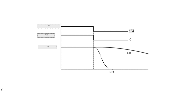
*1 Ignition Switch *2 OFF *3 Engine Speed *4 Fuel Pressure Result Result Proceed to Fuel pressure rises or drops moderately. A Fuel pressure drops immediately after turning the ignition switch off. B -
A
REPLACE FUEL INJECTOR ASSEMBLY (FOR DIRECT INJECTION) Click here
B
REPLACE FUEL PUMP ASSEMBLY (FOR HIGH PRESSURE) Click here
-
-
INSPECT FUEL INJECTOR ASSEMBLY (FOR PORT INJECTION)
-
Inspect the fuel injector assembly (for port injection) Click here.
OK
REPLACE ECM Click here
NG
REPLACE FUEL INJECTOR ASSEMBLY (FOR PORT INJECTION) Click here
-
-
CHECK HARNESS AND CONNECTOR (MASS AIR FLOW METER CONNECTOR CONNECTION)
-
Check the connection and terminal contact pressure of connectors and wire harness between the mass air flow meter and ECM Click here.
Tech Tips
Repair any problems.
NEXT
-
-
CLEAR DTC
-
Connect the GTS to the DLC3.
-
Turn the ignition switch to ON.
-
Turn the GTS on.
-
Clear the DTCs Click here.
NEXT
-
-
READ VALUE USING GTS (SHORT FT #1 AND LONG FT #1)
-
Connect the GTS to the DLC3.
-
Turn the ignition switch to ON.
-
Turn the GTS on.
-
Start the engine.
-
Enter the following menus: Powertrain / Engine / Data List / Short FT #1, Long FT #1
-
Read the value displayed on the GTS.
Standard GTS display Condition Specified condition Short FT #1 + Long FT #1 Vehicle condition when the malfunction occurs (Idling or driving) -20% to +20%
OK
END
NG
-
-
CHECK HARNESS AND CONNECTOR (MASS AIR FLOW METER - ECM)
-
Disconnect the mass air flow meter connector.
-
Disconnect the ECM connector.
-
Measure the resistance according to the value(s) in the table below.
Standard Resistance (Check for open) Tester Connection Condition Specified Condition A33-22 (VG) - C16-5 (VG) Always Below 1 Ω A33-29 (E2G) - C16-4 (E2G) Always Below 1 Ω Standard Resistance (Check for short) Tester Connection Condition Specified Condition A33-22 (VG) or C16-5 (VG) - Body ground Always 10 kΩ or higher A33-29 (E2G) or C16-4 (E2G) - Body ground Always 10 kΩ or higher
NG
REPAIR OR REPLACE HARNESS OR CONNECTOR
OK
-
-
REPLACE MASS AIR FLOW METER
-
Replace the mass air flow meter Click here.
Tech Tips
If the result of the inspection performed in step 8 indicated no problem, proceed to the next step without replacing the mass air flow meter.
NEXT
-
-
CLEAR DTC
-
Connect the GTS to the DLC3.
-
Turn the ignition switch to ON.
-
Turn the GTS on.
-
Clear the DTCs Click here.
NEXT
-
-
READ VALUE USING GTS (SHORT FT #1 AND LONG FT #1)
-
Connect the GTS to the DLC3.
-
Turn the ignition switch to ON.
-
Turn the GTS on.
-
Start the engine.
-
Enter the following menus: Powertrain / Engine / Data List / Short FT #1, Long FT #1.
-
Read the value displayed on the GTS.
Standard GTS display Condition Specified condition Short FT #1 + Long FT #1 Idling or racing -20% to +20% Tech Tips
If the trouble occurs during high speed driving, it is possible to take measurements at medium or low speeds by matching the intake air volume to that at the time of the trouble by shifting down.
OK
END
NG
REPLACE ECM Click here
-