ENGINE ASSEMBLY INSTALLATION
CAUTION / NOTICE / HINT
CAUTION:
The engine assembly with transaxle is very heavy. Be sure to follow the procedure described in the repair manual, or the engine lifter may suddenly drop.
PROCEDURE
-
INSTALL ENGINE HANGERS
-
REMOVE ENGINE ASSEMBLY FROM ENGINE STAND
-
Remove the engine assembly from the engine stand.
-
-
INSTALL NO. 1 IDLER PULLEY SUB-ASSEMBLY (w/o Air Conditioning System)
-
Using an E8 "TORX" socket wrench, install the 2 stud bolts.
- Torque:
- 9.8 N*m { 100 kgf*cm, 87 in.*lbf }
-
Install the No. 1 idler pulley sub-assembly.
-
Install the bolt and 2 nuts.
- Torque:
- 25 N*m { 255 kgf*cm, 18 ft.*lbf }
-
-
INSTALL NO. 1 IDLER PULLEY (w/o Air Conditioning System)
Tech Tips
Perform this procedure only when replacement of the No. 1 idler pulley is necessary.
-
Install the No. 1 idler pulley and 2 idler pulley cover plate to the idler pulley bracket with the bolt.
- Torque:
- 60 N*m { 612 kgf*cm, 44 ft.*lbf }
-
-
INSTALL COMPRESSOR WITH PULLEY ASSEMBLY (w/ Air Conditioning System)
-
INSTALL GENERATOR ASSEMBLY
-
for DENSO Made:
-
for VALEO Made:
-
-
INSTALL V-RIBBED BELT TENSIONER ASSEMBLY
-
Install the V-ribbed belt tensioner assembly to the timing chain cover assembly with the 2 bolts.
- Torque:
- 21 N*m { 214 kgf*cm, 15 ft.*lbf }
-
-
INSTALL FAN AND GENERATOR V BELT
-
INSTALL DRIVE PLATE AND RING GEAR SUB-ASSEMBLY (for CVT)
-
INSTALL FLYWHEEL SUB-ASSEMBLY (for Manual Transaxle)
-
INSTALL CLUTCH DISC ASSEMBLY (for Manual Transaxle)
-
w/o Stop and Start System:
-
w/ Stop and Start System:
-
-
INSTALL ENGINE ASSEMBLY (for CVT)
-
for 2WD:
-
for AWD:
-
-
INSTALL ENGINE ASSEMBLY (for Manual Transaxle)
-
w/o Stop and Start System:
-
w/ Stop and Start System:
-
-
INSTALL ENGINE WIRE
-
Connect all the connectors and clamps, and install the engine wire to the engine assembly with transaxle.
-
-
INSTALL FLYWHEEL HOUSING SIDE COVER
-
Install the flywheel housing side cover to the cylinder block sub-assembly.
-
-
INSTALL STARTER ASSEMBLY
-
for Denso Made with Stop and Start System:
-
for Denso Made without Stop and Start System:
-
for Valeo Made Cold Area Specification Vehicles:
-
for Valeo Made except Cold Area Specification Vehicles:
-
-
INSTALL WATER HOSE (for CVT)
-
Install the water hose to the engine assembly with transaxle and slide the 5 clips to secure it.
-
Engage the 3 clamps to the engine assembly with transaxle.
-
-
INSTALL WATER HOSE (for Manual Transaxle)
-
Install the water hose to the engine assembly with transaxle and slide the 3 clips to secure it.
-
Engage the 3 clamps to the engine assembly with transaxle.
-
-
INSTALL ENGINE MOUNTING INSULATOR SUB-ASSEMBLY RH (w/ Air Conditioning System)
Tech Tips
Perform this procedure only when replacement of the engine mounting insulator sub-assembly RH is necessary.
-
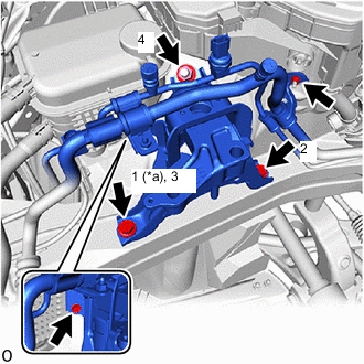
*a Temporarily Tighten Temporarily install the engine mounting insulator sub-assembly RH to the vehicle.
-
Install the 2 bolts and nut in the order shown in the illustration.
- Torque:
- 72 N*m { 734 kgf*cm, 53 ft.*lbf }
-
for DENSO Made:
-
Connect the air conditioner tube and accessory to the engine mounting insulator sub-assembly RH with the bolt and nut.
- Torque:
- 9.8 N*m { 100 kgf*cm, 87 in.*lbf }
-
-
for VALEO Made:
-
Connect the air conditioner tube and accessory to the engine mounting insulator sub-assembly RH with the bolt and nut.
- Torque:
- Bolt
- 9.8 N*m { 100 kgf*cm, 87 in.*lbf }
- Nut
- 5.4 N*m { 55 kgf*cm, 48 in.*lbf }
-
-
Install the No. 2 earth wire to the engine mounting insulator sub-assembly RH and vehicle with the 2 bolts.
- Torque:
- 10.5 N*m { 107 kgf*cm, 8 ft.*lbf }
-
-
INSTALL ENGINE MOUNTING INSULATOR SUB-ASSEMBLY RH (w/o Air Conditioning System)
Tech Tips
Perform this procedure only when replacement of the engine mounting insulator sub-assembly RH is necessary.
-
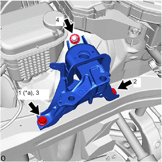
*a Temporarily Tighten Temporarily install the engine mounting insulator sub-assembly RH to the vehicle.
-
Install the 2 bolts and nut in the order shown in the illustration.
- Torque:
- 72 N*m { 734 kgf*cm, 53 ft.*lbf }
-
Install the No. 2 earth wire to the engine mounting insulator sub-assembly RH and vehicle with the 2 bolts.
- Torque:
- 10.5 N*m { 107 kgf*cm, 8 ft.*lbf }
-
-
INSTALL ENGINE MOUNTING INSULATOR LH
Tech Tips
Perform this procedure only when replacement of the engine mounting insulator LH is necessary.
-

*A for CVT *B for Manual Transaxle *a Temporarily Tighten Temporarily install the engine mounting insulator LH to the vehicle.
-
Install the 4 bolts and nut in the order shown in the illustration.
- Torque:
- 42 N*m { 428 kgf*cm, 31 ft.*lbf }
-
-
REMOVE ENGINE HANGERS
-
INSTALL WIRE HARNESS CLAMP BRACKET
-
Install the wire harness clamp bracket to the cylinder head sub-assembly with the bolt.
- Torque:
- 39 N*m { 398 kgf*cm, 29 ft.*lbf }
-
Install the engine wire to the wire harness clamp bracket with the nut.
- Torque:
- 10 N*m { 102 kgf*cm, 7 ft.*lbf }
-
Engage the 3 clamps.
-
-
INSTALL ENGINE ASSEMBLY WITH TRANSAXLE
-
Using height adjustment attachments and plate lift attachments to keep the engine assembly with transaxle and front suspension crossmember sub-assembly level, set an engine lifter underneath the engine assembly with transaxle and front suspension crossmember sub-assembly.
Note
-
Using height adjustment attachments and plate lift attachments, keep the engine assembly with transaxle horizontal.
-
Do not perform any procedures while the engine assembly is suspended because doing so may cause the engine assembly to drop, resulting in injury. However, the engine assembly needs to be suspended when it is installed to or removed from an engine stand.
-
To prevent the oil pan sub-assembly from deforming, do not place any attachments under the oil pan sub-assembly of the engine assembly with transaxle.
-
-
Operate the engine lifter and install the engine assembly with transaxle to the vehicle.
CAUTION:
Do not raise the engine assembly with transaxle more than necessary. If the engine is raised excessively, the vehicle may also be lifted up.
Note
-
Make sure that the engine assembly with transaxle is clear of all wiring and hoses.
-
While raising the engine assembly with transaxle into the vehicle, do not allow it to contact the vehicle.
-
-
Connect the front suspension crossmember sub-assembly to the vehicle with the 6 bolts.
- Torque:
- 141 N*m { 1438 kgf*cm, 104 ft.*lbf }
-
Install the engine mounting insulator LH to the engine mounting bracket LH with the bolt and nut.
- Torque:
- 44 N*m { 449 kgf*cm, 32 ft.*lbf }
Note
While holding the nut in place, tighten the bolt.
-
Install the engine mounting insulator sub-assembly RH to the engine mounting bracket RH with the 2 bolts and nut.
- Torque:
- Bolt
- 72 N*m { 734 kgf*cm, 53 ft.*lbf }
- Nut
- 41 N*m { 418 kgf*cm, 30 ft.*lbf }
-
-
INSTALL REAR SIDE RAIL REINFORCEMENT SUB-ASSEMBLY LH
-
INSTALL REAR SIDE RAIL REINFORCEMENT SUB-ASSEMBLY RH
Tech Tips
Use the same procedure as for the LH side.
-
INSTALL DRIVE PLATE AND TORQUE CONVERTER ASSEMBLY SETTING BOLT (for CVT)
-
for 2WD:
-
for AWD:
-
-
INSTALL FLYWHEEL HOUSING UNDER COVER (for CVT)
-
for 2WD:
-
for AWD:
-
-
CONNECT NO. 1 CLUTCH HOSE (for Manual Transaxle)
-
Connect the No. 1 clutch hose to the clutch flexible hose bracket with a new clip.
-
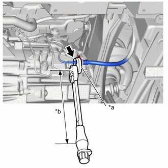
*a 10 mm Union Nut Wrench *b Torque Wrench Fulcrum Length Using a 10 mm union nut wrench, connect the bleeder clutch release tube to the No. 1 clutch hose.
- Torque:
- Specified tightening torque
- 15.2 N*m { 155 kgf*cm, 11 ft.*lbf }
Tech Tips
-
Calculate the torque wrench reading when changing the fulcrum length of the torque wrench.
-
When using a 10 mm union nut wrench (fulcrum length of 22 mm (0.866 in.)) + torque wrench (fulcrum length of 162 mm (6.38 in.)): 13.4 N*m (137 kgf*cm, 10 ft.*lbf)
-
-
INSTALL FRONT DRIVE SHAFT ASSEMBLY
-
for TMC Made:
-
for TMMT Made:
-
-
INSTALL PROPELLER WITH CENTER BEARING SHAFT ASSEMBLY (for AWD)
-
INSTALL FRONT EXHAUST PIPE ASSEMBLY (TWC: Rear Catalyst) (for 2WD)
-
INSTALL FRONT EXHAUST PIPE ASSEMBLY (for AWD)
-
INSTALL NO. 2 CENTER EXHAUST PIPE ASSEMBLY (TWC: Rear Catalyst) (for AWD)
-
INSTALL FRONT FLOOR CENTER BRACE (for 2WD)
-
INSTALL FRONT FLOOR CENTER BRACE (for AWD)
-
INSTALL FRONT FLOOR COVER LH (w/ Cover)
-
INSTALL FRONT FLOOR COVER RH (w/ Cover)
Tech Tips
Use the same procedure as for the LH side.
-
CONNECT NO. 1 STEERING COLUMN HOLE COVER SUB-ASSEMBLY
-
CONNECT NO. 2 STEERING INTERMEDIATE SHAFT ASSEMBLY
-
INSTALL COLUMN HOLE COVER SILENCER SHEET
-
CONNECT SUCTION HOSE SUB-ASSEMBLY (w/ Air Conditioning System)
-
CONNECT DISCHARGE HOSE SUB-ASSEMBLY (w/ Air Conditioning System)
-
CONNECT FUEL TUBE SUB-ASSEMBLY
-
CONNECT INLET HEATER WATER HOSE
-
CONNECT OUTLET HEATER WATER HOSE
-
CONNECT FUEL VAPOR FEED HOSE
-
Connect the fuel vapor feed hose to the fuel vapor feed pipe and slide the clip to secure it.
-
-
CONNECT UNION TO CONNECTOR TUBE HOSE
-
CONNECT TRANSMISSION CONTROL CABLE ASSEMBLY (for CVT)
-
for 2WD:
-
for AWD:
-
-
CONNECT TRANSMISSION CONTROL CABLE ASSEMBLY (for Manual Transaxle)
-
w/o Stop and Start System:
-
w/ Stop and Start System:
-
-
CONNECT NO. 4 INTERCOOLER COOLING WATER HOSE
-
CONNECT NO. 1 INTERCOOLER COOLING WATER HOSE
-
CONNECT NO. 2 RADIATOR HOSE
-
Connect the No. 2 radiator hose to the water inlet with thermostat sub-assembly and slide the clip to secure it.
-
-
CONNECT NO. 1 RADIATOR HOSE
-
Connect the No. 1 radiator hose to the water outlet and slide the clip to secure it.
-
-
INSTALL BATTERY CLAMP SUB-ASSEMBLY
-
Install the battery clamp sub-assembly to the vehicle with the 3 bolts.
- Torque:
- 15.4 N*m { 157 kgf*cm, 11 ft.*lbf }
-
Engage the clamp to connect the engine wire to the battery clamp sub-assembly.
-
-
CONNECT WIRE HARNESS
-
Connect the engine wire to the transaxle assembly with the bolt.
- Torque:
- 8.5 N*m { 87 kgf*cm, 75 in.*lbf }
-
Connect the engine wire to the positive (+) battery terminal with the 3 nuts.
- Torque:
- 7.6 N*m { 77 kgf*cm, 67 in.*lbf }
-
Connect the engine wire to the battery clamp sub-assembly with the bolt and nut.
- Torque:
- 7.0 N*m { 71 kgf*cm, 62 in.*lbf }
-
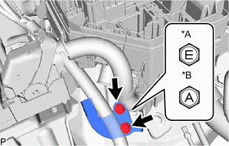
*A for Type A *B for Type B Connect the engine wire to the vehicle with the 2 bolts.
- Torque:
- for Type A
- 8.5 N*m { 87 kgf*cm, 75 in.*lbf }
- for Type B
- 10.5 N*m { 107 kgf*cm, 8 ft.*lbf }
-
-
INSTALL ECM
-
INSTALL AIR CLEANER CASE SUB-ASSEMBLY
-
Install the air cleaner case sub-assembly to the vehicle with the 2 bolts.
- Torque:
- 4.0 N*m { 41 kgf*cm, 35 in.*lbf }
-
Install the air cleaner filter element sub-assembly to the air cleaner case sub-assembly.
-
-
INSTALL AIR CLEANER CAP WITH AIR CLEANER HOSE
-
Connect the air cleaner cap with air cleaner hose and tighten the hose clamp.
- Torque:
- 2.0 N*m { 20 kgf*cm, 18 in.*lbf }
-
Engage the 2 guides to install the air cleaner cap sub-assembly to the air cleaner case sub-assembly.
-
Engage the 2 air cleaner cap sub-assembly clamps to install the air cleaner cap sub-assembly.
-
Engage the clamp to the air cleaner cap sub-assembly.
-
Connect the mass air flow meter connector.
-
-
INSTALL NO. 1 AIR CLEANER INLET
-
INSTALL RADIATOR COVER
-
INSTALL OUTER COWL TOP PANEL SUB-ASSEMBLY (for LHD)
-
INSTALL OUTER COWL TOP PANEL SUB-ASSEMBLY (for RHD)
-
INSTALL COWL BODY MOUNTING REINFORCEMENT RH
-
INSTALL COWL BODY MOUNTING REINFORCEMENT LH
-
INSTALL WATER GUARD PLATE LH
-
INSTALL NO. 1 HEATER AIR DUCT SPLASH SHIELD SEAL
-
INSTALL WINDSHIELD WIPER MOTOR AND LINK
-
INSTALL BATTERY
-
CONNECT CABLE TO NEGATIVE BATTERY TERMINAL
Note
When disconnecting the cable, some systems need to be initialized after the cable is reconnected.
-
BLEED CLUTCH LINE (for Manual Transaxle)
-
w/o Stop and Start System:
-
w/ Stop and Start System:
-
-
ADD ENGINE OIL
-
ADD ENGINE COOLANT
-
ADD COOLANT (for Intercooler)
-
ADD MANUAL TRANSAXLE OIL (for Manual Transaxle)
-
w/o Stop and Start System:
-
w/ Stop and Start System:
-
-
ADD CONTINUOUSLY VARIABLE TRANSAXLE FLUID (for CVT)
-
for 2WD:
-
for AWD:
-
-
ADD TRANSFER OIL (for AWD)
-
CHARGE AIR CONDITIONING SYSTEM WITH REFRIGERANT (w/ Air Conditioning System)
-
for HFC-134a (R134a):
-
for HFO-1234yf (R1234yf):
-
-
WARM UP ENGINE (w/ Air Conditioning System)
-
Keep the A/C switch on for at least 2 minutes to warm up the compressor.
Note
To prevent damage to the compressor, be sure to warm up the compressor when turning the air conditioning on after removing and installing any air conditioning system lines (including the compressor).
-
-
INSPECT TRANSAXLE OIL (for Manual Transaxle)
-
w/o Stop and Start System:
-
w/ Stop and Start System:
-
-
ADJUST SHIFT LEVER POSITION (for Manual Transaxle)
-
w/o Stop and Start System:
-
w/ Stop and Start System:
-
-
INSPECT SHIFT LEVER POSITION (for CVT)
-
for 2WD:
-
for AWD:
-
-
ADJUST SHIFT LEVER POSITION (for CVT)
-
for 2WD:
-
for AWD:
-
-
INSPECT FOR ENGINE OIL LEAK
-
INSPECT FOR COOLANT LEAK
-
INSPECT FOR COOLANT LEAK (for Intercooler)
-
INSPECT FOR CONTINUOUSLY VARIABLE TRANSAXLE FLUID LEAK (for CVT)
-
INSPECT MANUAL TRANSAXLE OIL LEAK (for Manual Transaxle)
-
INSPECT FOR REFRIGERANT LEAK (w/ Air Conditioning System)
-
for HFC-134a (R134a):
-
for HFO-1234yf (R1234yf):
-
-
INSPECT FOR FUEL LEAK
-
INSPECT FOR EXHAUST GAS LEAK
-
CHECK ENGINE OIL LEVEL
-
INSPECT ENGINE COOLANT LEVEL IN RESERVOIR
-
INSTALL REAR ENGINE UNDER COVER LH
-
Install the rear engine under cover LH to the vehicle with the 6 clips.
-
-
INSTALL REAR ENGINE UNDER COVER RH
-
Install the rear engine under cover RH to the vehicle with the 6 clips.
-
-
INSTALL NO. 1 ENGINE UNDER COVER
-
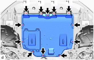
*1 Bolt Install the No. 1 engine under cover to the vehicle with the 4 bolts, 4 screws and 4 clips.
- Torque:
- Bolt
- 7.5 N*m { 76 kgf*cm, 66 in.*lbf }
-
-
INSTALL FRONT WHEELS
-
ALIGN FRONT WHEELS FACING STRAIGHT AHEAD
-
INSPECT AND ADJUST FRONT WHEEL ALIGNMENT
-
PERFORM INITIALIZATION
-
INSPECT IGNITION TIMING
-
INSPECT ENGINE IDLE SPEED
-
INSPECT CO/HC
-
CHECK SPEED SENSOR SIGNAL