VACUUM PUMP(When Using the Engine Support Bridge for AD Series Engine) REMOVAL
PROCEDURE
REMOVE WINDSHIELD WIPER ARM COVER
REMOVE WINDSHIELD WIPER ARM AND BLADE ASSEMBLY LH
REMOVE WINDSHIELD WIPER ARM AND BLADE ASSEMBLY RH
REMOVE COWL TOP VENTILATOR LOUVER SUB-ASSEMBLY
REMOVE NO. 1 ENGINE COVER
REMOVE AIR CLEANER CAP SUB-ASSEMBLY
REMOVE AIR CLEANER FILTER ELEMENT SUB-ASSEMBLY
REMOVE AIR CLEANER CASE
REMOVE REAR ENGINE UNDER COVER RH
INSTALL ENGINE HANGER
DISCONNECT RADIATOR RESERVE TANK ASSEMBLY
INSTALL ENGINE SUPPORT BRIDGE
Install SST to the vehicle body as shown in the illustration.
09940-10020
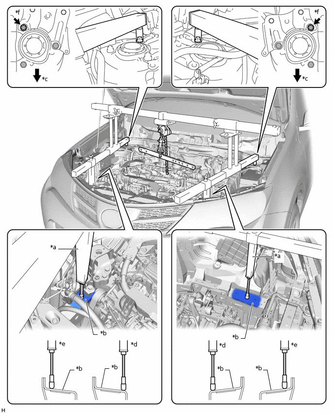
*a
Support Shaft
*b
Side Member
*c
Front Side
*d
Incorrect
*e
Correct
*f
Front Suspension Nut
CAUTION:-
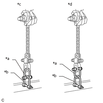
*a
Fuse Shackle
*b
Shackle (A)
*c
Correct
*d
Incorrect
Make sure the fuse shackle is on the chain block side and the shackle (A) is on the division bar side as shown in the illustration so that the fuse bolt is visible and can be checked for deformation easily.
-
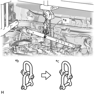
*a
Fuse Bolt
*b
Correct
*c
Incorrect
Make sure the fuse bolt is not deformed.
Note:Prevent SST from contacting the vehicle body or windshield.
Lightly shake SST by hand to make sure it is securely installed while performing work.
Set the support shafts on level surfaces.
To prevent damage to the engine hood, place pieces of cloth between the engine hood and SST.
-
-
*a
Support Shaft
*b
Sub Beam
*c
Side Member
*d
Threaded Portion
Turn the threaded portion of each support shaft to adjust its height and make the SST sub beams parallel to the ground.
Connect the chain to the division bar with the shackle at the position shown in the illustration.
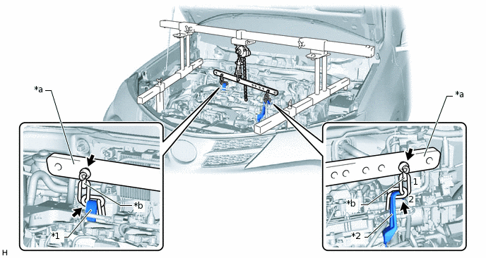
*1
No. 1 Engine Hanger
*2
No. 2 Engine Hanger
*a
Division Bar
*b
Shackle
Connect the division bar and No. 1 engine hanger with the shackle.
Connect the 2nd link of the chain to the No. 2 engine hanger.
Make sure the distance between A and B is 120 mm (4.72 in.) or more.
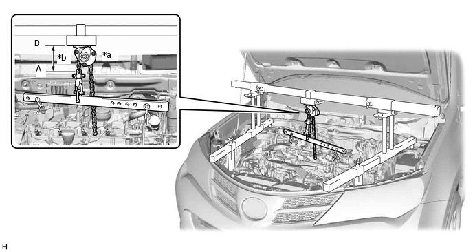
*a
Chain Block Assembly
*b
120 mm (4.72 in.) or more
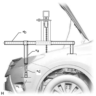
Adjust the position of the chain block assembly so that the chain is perpendicular to the SST main beam and sub beams as shown in the illustration.
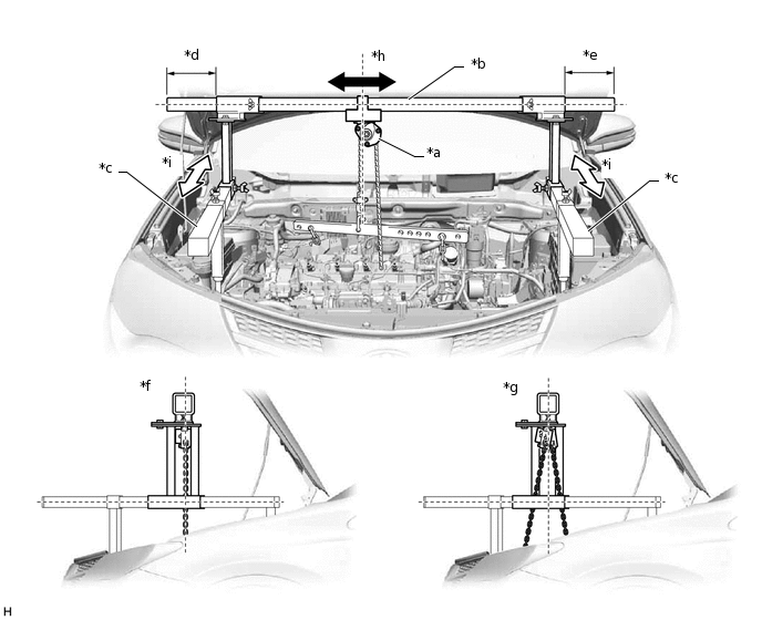
*a
Chain Block Assembly
*b
Main Beam
*c
Sub Beam
*d
Dimension (A)
*e
Dimension (B)
*f
Correct
*g
Incorrect
*h
Right to Left Adjustment
*i
Front to Rear Adjustment
-
-
CAUTION:To prevent the engine with automatic transaxle assembly from falling, make sure that the dimension (A) and dimension (B) are equal.
Tighten the 6 wing bolts and 2 bolts.
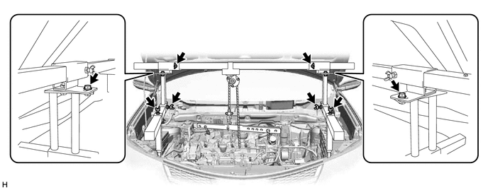
for bolt
30 N*m
306 kgf*cm
22 ft.*lbf
-


Turn
Tighten the chain block assembly until it cannot be moved any further by hand.
CAUTION: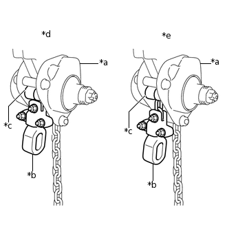
*a
Chain Block Assembly
*b
Suspension Ring
*c
Roller
*d
Incorrect
*e
Correct
If the suspension ring contacts the roller of the chain block assembly, the chain block assembly may be damaged. Do not tighten the chain block assembly excessively.
Note:When suspending the engine with automatic transaxle assembly, do not tighten the chain block assembly more than 50 N*m (510 kgf*cm, 37 ft.*lbf).
Do not shake the engine with automatic transaxle assembly excessively while it is being suspended.
REMOVE ENGINE MOUNTING INSULATOR SUB-ASSEMBLY RH
-
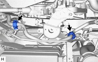
Disconnect the 2 clamps from the suction tube sub-assembly.
-
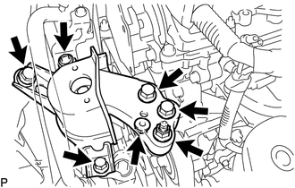
Remove the 2 nuts, 5 bolts and engine mounting insulator sub-assembly RH.
Note:Do not damage the suction tube sub-assembly.
-
REMOVE VACUUM PUMP ASSEMBLY
-
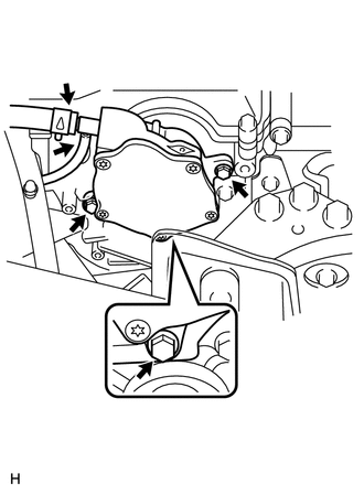
Slide the clip and disconnect the 2 vacuum hoses.
Remove the 3 bolts and vacuum pump.
Remove the 2 O-rings from the vacuum pump.
-