POWER SLIDE DOOR SYSTEM Slide Door Handle Switch LH Circuit
DESCRIPTION
When the power slide door ECU LH receives a switch signal from the slide door lock remote control LH (position switch), the power slide door ECU LH restricts operation of the power slide door.
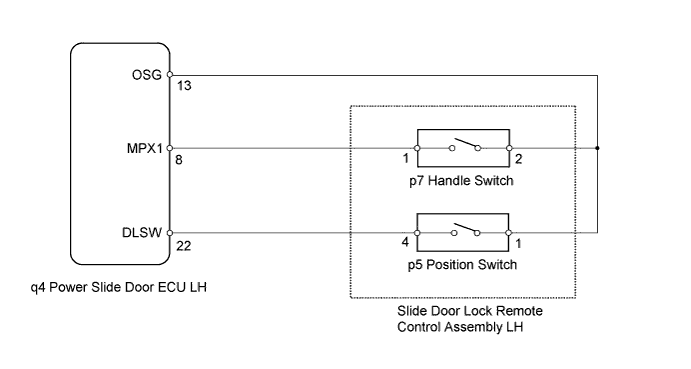
WIRING DIAGRAM
INSPECTION PROCEDURE
PROCEDURE
-
INSPECT SLIDE DOOR LOCK REMOTE CONTROL ASSEMBLY LH (HANDLE SWITCH)
-
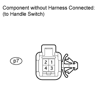
Disconnect the p7 connector from the slide door lock remote control assembly LH (handle switch).
-
Measure the resistance of the handle switch.
Standard resistance Tester Connection Switch Condition Specified Condition p7-1 - p7-2 Handle in initial position 10 kΩ or higher p7-1 - p7-2 Handle pulled Below 1 Ω
NG 
REPLACE SLIDE DOOR LOCK REMOTE CONTROL ASSEMBLY LH
OK 
-
-
INSPECT SLIDE DOOR LOCK REMOTE CONTROL ASSEMBLY LH (POSITION SWITCH)
-
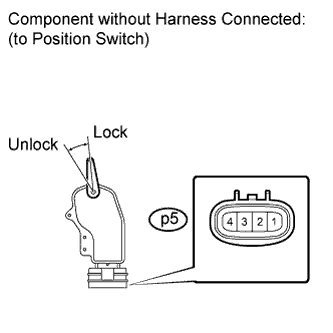
Disconnect the p5 connector from the slide door lock remote control assembly LH (position switch in the actuator).
-
Measure the resistance of the position switch.
Standard resistance Tester Connection Door Lock Condition Specified Condition p5-1 - p5-4 Lock 10 kΩ or higher p5-1 - p5-4 Unlock Below 1 Ω
NG
REPLACE SLIDE DOOR LOCK REMOTE CONTROL ASSEMBLY LH
OK
-
-
CHECK HARNESS AND CONNECTOR (HANDLE SWITCH CIRCUIT)
-
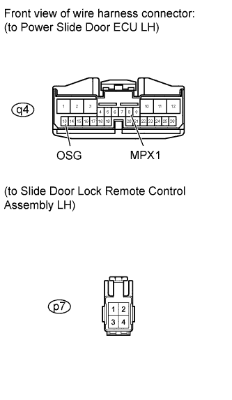
Disconnect the q4 connector from the power slide door ECU LH.
-
Measure the resistance.
Standard resistance Tester Connection Condition Specified Condition q4-8 (MPX1) - p7-1 Always Below 1 Ω q4-13 (OSG) - p7-2 Always Below 1 Ω
NG
REPAIR OR REPLACE HARNESS OR CONNECTOR
OK
-
-
CHECK HARNESS AND CONNECTOR (POSITION SWITCH CIRCUIT)
-
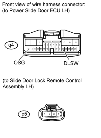
Disconnect the q4 connector from the power slide door ECU LH.
-
Measure the resistance.
Standard resistance Tester Connection Condition Specified Condition q4-22 (DLSW) - p5-4 Always Below 1 Ω q4-13 (OSG) - p5-1 Always Below 1 Ω
NG
REPAIR OR REPLACE HARNESS OR CONNECTOR
OK 
REPLACE POWER SLIDE DOOR ECU LH
-