IMMOBILISER SYSTEM(w/o Entry and Start System) TERMINALS OF ECU
CHECK TRANSPONDER KEY ECU ASSEMBLY
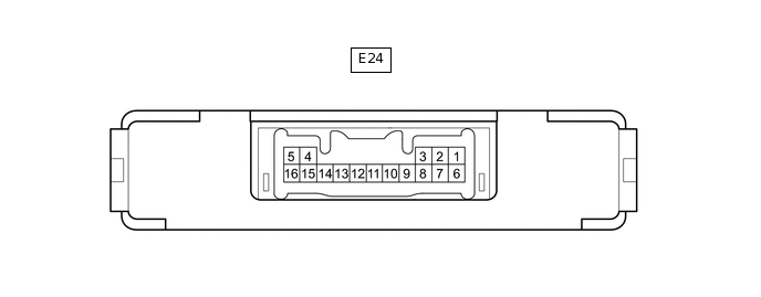
Disconnect the E24 transponder key ECU assembly connector.
Measure the resistance and voltage according to the value(s) in the table below.
Tip:Measure the values on the wire harness side with the connector disconnected.
Terminal No. (Symbol)
Input/Output
Wiring Color
Terminal Description
Condition
Specified Condition
Related Data List Item/DTC
E24-1 (+B) - E24-5 (GND)
Input
R - W-B
Battery
Always
11 to 14 V
+B
E24-2 (IG) - E24-5 (GND)
Input
B - W-B
Ignition switch signal
Ignition switch off
Below 1 V
IG SW
Ignition switch ON
11 to 14 V
E24-5 (GND) - Body ground
-
W-B - Body ground
Ground
Always
Below 1 Ω
-
Reconnect the E24 transponder key ECU assembly connector.
Measure the voltage and check for pulses according to the value(s) in the table below.
Terminal No. (Symbol)
Input/Output
Wiring Color
Terminal Description
Condition
Specified Condition
Related Data List Item/DTC
E24-9 (D) - E24-5 (GND)
Input/Output
W - W-B
DLC3 communication
Without communication
Below 1 V
-
During communication
Pulse generation
E24-4 (ANT1) - E24-5 (GND)
Input/Output
L - W-B
Transponder key amplifier power source
No door control transmitter assembly in ignition key cylinder
4 to 6 V
-
Within 3 seconds of ignition switch turned to ON
Pulse generation
(See waveform 1)
E24-15 (ANT2) - E24-5 (GND)
Input/Output
LG - W-B
Transponder key amplifier communication signal
No door control transmitter assembly in ignition key cylinder
4 to 6 V
-
Within 3 seconds of ignition switch turned to ON
Pulse generation
(See waveform 2)
E24-12 (EFII) - E24-5 (GND)
Input
GR - W-B
ECM input signal
Within 3 seconds of starter operation and initial combustion, or within 3 seconds of ignition switch first being turned to ON after cable disconnected and reconnected to negative (-) battery terminal
Pulse generation
(See waveform 3)
-
E24-13 (EFIO) - E24-5 (GND)
Output
V - W-B
ECM output signal
Ignition switch off
Below 1 V
-
Within 3 seconds of starter operation and initial combustion, or within 3 seconds of ignition switch first being turned to ON after cable disconnected and reconnected to negative (-) battery terminal
Pulse generation
(See waveform 4)
-
Using an oscilloscope, check the waveform.
Waveform 1 (Reference)
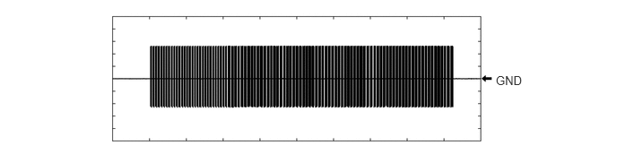
Table 1. Measurement Condition Item
Content
Tester Connection
E24-4 (ANT1) - E24-5 (GND)
Tool Setting
2 V/DIV., 500 ms./DIV.
Condition
Within 3 seconds of ignition switch turned to ON
Waveform 2 (Reference)
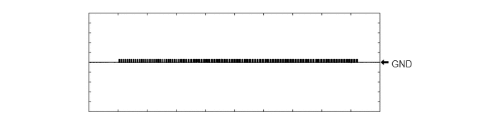
Table 2. Measurement Condition Item
Content
Tester Connection
E24-15 (ANT2) - E24-5 (GND)
Tool Setting
2 V/DIV., 500 ms./DIV.
Condition
Within 3 seconds of ignition switch turned to ON
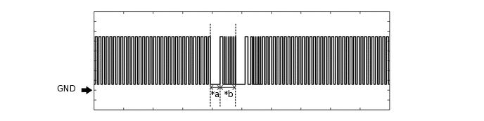
Waveform 3 (Reference)
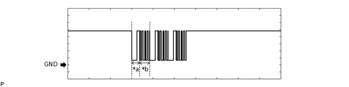
*a
Approximately 160 ms
*b
Approximately 270 ms
Table 3. Measurement Condition Item
Content
Tester Connection
E24-12 (EFII) - E24-5 (GND)
Tool Setting
2 V/DIV., 500 ms./DIV.
Condition
Within 3 seconds of starter operation and initial combustion, or within 3 seconds of ignition switch first being turned to ON after cable disconnected and reconnected to negative (-) battery terminal
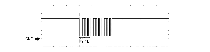
Waveform 4 (Reference)
*a
Approximately 160 ms
*b
Approximately 270 ms
Table 4. Measurement Condition Item
Content
Tester Connection
E24-13 (EFIO) - E24-5 (GND)
Tool Setting
2 V/DIV., 500 ms./DIV.
Condition
Within 3 seconds of starter operation and initial combustion, or within 3 seconds of ignition switch first being turned to ON after cable disconnected and reconnected to negative (-) battery terminal
CHECK ECM (for 1KR-FE)
Measure the voltage and resistance, and check for pulses according to the value(s) in the table below.
Terminal No. (Symbol)
Input/Output
Wiring Color
Terminal Description
Condition
Specified Condition
Related Data List Item / DTC
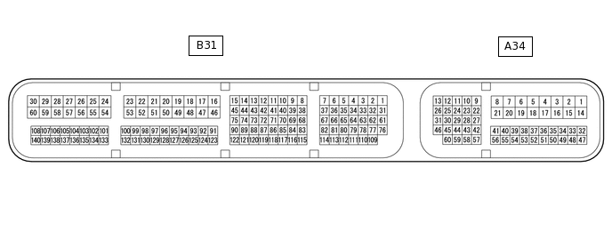
A34-4 (E1) - Body ground
-
W-B - Body ground
Ground
Always
Below 1 Ω
-
A34-5 (E01) - Body ground
-
W-B - Body ground
Ground
Always
Below 1 Ω
-
A34-17 (E02) - Body ground
-
W-B - Body ground
Ground
Always
Below 1 Ω
-
A34-15 (BATT) - A34-4 (E1)
Input
SB - W-B
Battery (for measuring battery voltage and for ECM memory)
Always
11 to 14 V
-
A34-1 (+B1) - A34-4 (E1)
Input
B - W-B
Power source of ECM
Ignition switch ON
11 to 14 V
-
A34-2 (+B) - A34-4 (E1)
Input
B - W-B
Power source of ECM
Ignition switch ON
11 to 14 V
-
A34-43 (IMO) - A34-4 (E1)
Output
GR - W-B
Transponder key ECU assembly communication output
Within 3 seconds of starter operation and initial combustion, or within 3 seconds of ignition switch first being turned to ON after cable disconnected and reconnected to negative (-) battery terminal
Pulse generation
(See waveform 1)
-
A34-42 (IMI) - A34-4 (E1)
Input
V - W-B
Transponder key ECU assembly communication input
Ignition switch off
Below 1 V
-
Within 3 seconds of starter operation and initial combustion, or within 3 seconds of ignition switch first being turned to ON after cable disconnected and reconnected to negative (-) battery terminal
Pulse generation
(See waveform 2)
-
Using an oscilloscope, check the waveform.
Waveform 1 (Reference)
*a
Approximately 160 ms
*b
Approximately 270 ms
Tester Connection
A34-43 (IMO) - A34-4 (E1)
Tool Setting
2 V/DIV., 500 ms./DIV.
Condition
Within 3 seconds of starter operation and initial combustion, or within 3 seconds of ignition switch first being turned to ON after cable disconnected and reconnected to negative (-) battery terminal
Waveform 2 (Reference)
*a
Approximately 160 ms
*b
Approximately 270 ms
Tester Connection
A34-42 (IMI) - A34-4 (E1)
Tool Setting
2 V/DIV., 500 ms./DIV.
Condition
Within 3 seconds of starter operation and initial combustion, or within 3 seconds of ignition switch first being turned to ON after cable disconnected and reconnected to negative (-) battery terminal
-
CHECK ECM (for 1PP)
Measure the voltage and resistance, and check for pulses according to the value(s) in the table below.
Terminal No. (Symbol)
Input/Output
Wiring Color
Terminal Description
Condition
Specified Condition
Related Data List Item / DTC
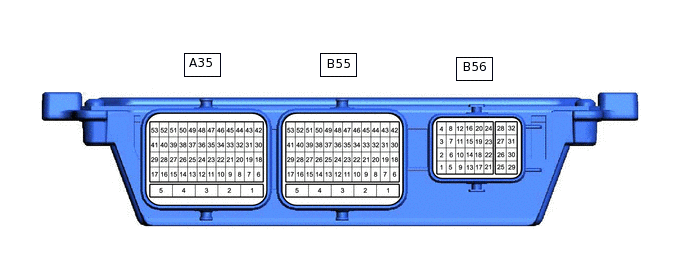
A35-53 (GND1) - Body ground
-
W-B - Body ground
Ground
Always
Below 1 Ω
-
A35-4 (GND2) - Body ground
-
W-B - Body ground
Ground
Always
Below 1 Ω
-
A35-3 (GND3) - Body ground
-
W-B - Body ground
Ground
Always
Below 1 Ω
-
A35-5 (+B1) - A35-53 (GND1)
Input
B - W-B
Power source of ECM
Ignition switch ON
11 to 14 V
-
B56-18 (IMO) - A35-53 (GND1)
Output
GR - W-B
Transponder key ECU assembly communication output
Within 3 seconds of starter operation and initial combustion, or within 3 seconds of ignition switch first being turned to ON after cable disconnected and reconnected to negative (-) battery terminal
Pulse generation
(See waveform 1)
-
B56-19 (IMI) - A35-53 (GND1)
Input
V - W-B
Transponder key ECU assembly communication input
Ignition switch off
Below 1 V
-
Within 3 seconds of starter operation and initial combustion, or within 3 seconds of ignition switch first being turned to ON after cable disconnected and reconnected to negative (-) battery terminal
Pulse generation
(See waveform 2)
-
Using an oscilloscope, check the waveform.
Waveform 1 (Reference)
*a
Approximately 160 ms
*b
Approximately 270 ms
Tester Connection
B56-18 (IMO) - A35-53 (GND1)
Tool Setting
2 V/DIV., 500 ms./DIV.
Condition
Within 3 seconds of starter operation and initial combustion, or within 3 seconds of ignition switch first being turned to ON after cable disconnected and reconnected to negative (-) battery terminal
Waveform 2 (Reference)
*a
Approximately 160 ms
*b
Approximately 270 ms
Tester Connection
B56-19 (IMI) - A35-53 (GND1)
Tool Setting
2 V/DIV., 500 ms./DIV.
Condition
Within 3 seconds of starter operation and initial combustion, or within 3 seconds of ignition switch first being turned to ON after cable disconnected and reconnected to negative (-) battery terminal