MILLIMETER WAVE RADAR SENSOR ADJUSTMENT

PROCEDURE
-
ADJUST MILLIMETER WAVE RADAR SENSOR ASSEMBLY
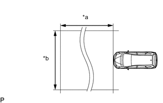
Text in Illustration *a Approximately 10 m (32.8 ft.) *b Approximately 14 m (45.9 ft.) Note
-
Perform measurements on a level surface.
-
Make sure that no large pieces of metal are within a 10 m (32.8 ft.) x 14 m (45.9 ft.) area in front of the vehicle. If possible, the surrounding area should also be free of large metal objects.
-
Before adjusting the radar beam axis, prepare the vehicle as follows.
-
Check the tire pressure and adjust it if necessary.
-
Remove all excess weight from the vehicle (luggage, heavy objects, etc.).
-
Remove the radiator support opening cover Click here.
-
-
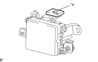
Text in Illustration *a Level Check and adjust the vertical direction of the radar sensor.
-
Remove dust, oil and foreign matter from the radar sensor's level rack.
-
Set a level on the radar sensor's level rack.
-
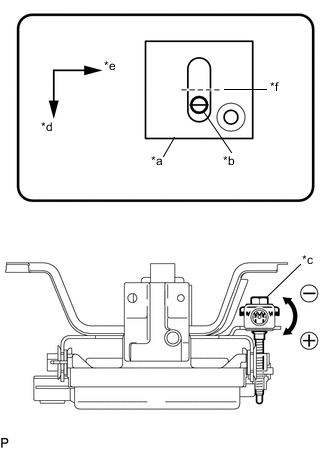
Text in Illustration *a Level *b Air Bubble *c Bolt *d Vehicle Front *e Vehicle Left *f 0° Check that the level's air bubble is within the red frame.
OK Level's air bubble is within red frame. If the bubble is not within the red frame, use a screwdriver to adjust bolt until the air bubble is within the red frame.
Tech Tips
-
The adjustable range within the level's red frame is +/- 0.2°.
-
The target angle is +0.2° (upward angle of 0.2°).
Adjustment Adjustment Direction Adjustment Procedure Adjustment Angle Upward Turn screwdriver to positive (+) side When screwdriver is turned once, adjustment changes by about Downward 0.12° Downward Turn screwdriver to negative (-) side
-
-
-
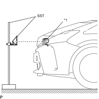
Text in Illustration *1 Millimeter Wave Radar Sensor Adjust the reflector height.
-
Adjust the reflector so that the center of SST (reflector) is the same height as the millimeter wave radar sensor.
- SST
- 09870-60000 ( 09870-60010 )
- 09870-60040
Tech Tips
Prepare a 10 m (32.8 ft.) string, a string with a sharp-pointed weight (plumb bob) and a 5 m (16.4 ft.) tape measure.
-
-
Place the reflector.
-
Hang the string (with weight) from the center of the vehicle rear emblem. Mark the vehicle rear center point on the ground.
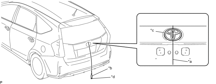
Text in Illustration *a String *b Weight *c Center point *d Mark -
Repeat for the front of the vehicle.
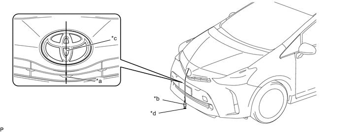
Text in Illustration *a String *b Weight *c Center point *d Mark -
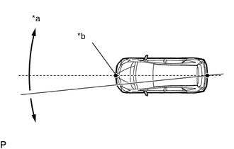
Text in Illustration *a Adjust center by moving string to right and left *b Extend string through front center point Set one end of the 10 m (32.8 ft.) string on the vehicle rear center point. Run the string over the vehicle front center point to a position 5 m (16.4 ft.) beyond the vehicle front center point, as shown in the illustration. Mark the 5 m (16.4 ft.) position.
-
Place the reflector (SST) at the marked position.
Note
Perform the operation as precisely as possible.
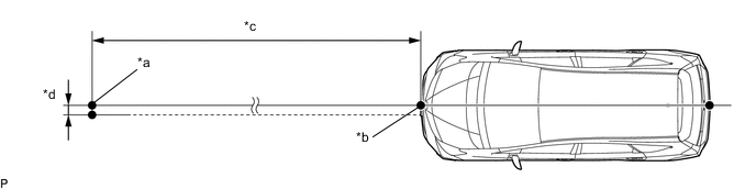
Text in Illustration *a Reflector Placement Point *b Millimeter Wave Radar Sensor Position *c 5000 mm (16.4 ft.) *d 7.5 mm (0.295 in.)
-
-
Check the radar beam axis.
-
When using the GTS:
-
Connect the GTS to the DLC3.
-
Turn the power switch on (IG).
-
Turn the GTS on and turn the cruise control main switch on.
-
Select "Connect to Vehicle".
-
Select each item on the display screen and proceed to the next screen.
-
Under "System Selection Menu", select "Radar Cruise".
-
Select "Utility" from the display screen.
-
Select "Beam Axis Adjustment" and proceed to the next screen.
-
Follow the GTS display and continue with the adjustment.
CAUTION:
Do not come within 20 cm (7.87 in.) of the radar sensor.
Note
-
Turn the cruise control main switch on before pressing "Next".
-
Make sure there is at least 20 cm (7.87 in.) between the millimeter wave radar sensor and any nearby individuals.
-
If "Error beam axis" is displayed on the screen, press the "Yes" button, and repeat again.
-
Check that there are no metal objects in the specified area in front of the vehicle (refer to the NOTICE at the beginning of this adjustment procedure).
-
-
-
Press the "Exit" button to finish beam axis adjustment.
-
Disconnect the GTS from the DLC3.
-
-
After adjusting the radar beam axis, return the vehicle to its original condition.
-
Install the radiator support opening cover Click here.
-
If any heavy items were removed from the vehicle, return them (luggage, heavy objects, etc.).
-
-