THEFT DETERRENT SYSTEM Glass Breakage Sensor Circuit
DESCRIPTION
When the main body ECU (multiplex network body ECU) detects that the glass breakage sensor (back door glass) is broken, the theft deterrent system switches from the armed state to the alarm sounding state.
WIRING DIAGRAM
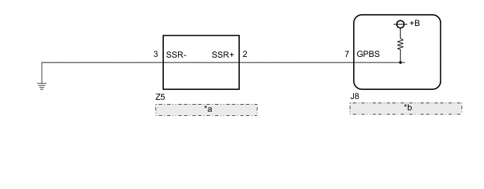
| *a | Glass Breakage Sensor (Back Door Glass) |
| *b | Main Body ECU (Multiplex Network Body ECU) |
CAUTION / NOTICE / HINT
Note
The vehicle battery supplies power to the main body ECU (multiplex network body ECU) via the door control battery. Therefore, before proceeding with troubleshooting, perform an on-vehicle inspection and confirm that the main body ECU (multiplex network body ECU) power source circuit is normal.*
-
*: w/o Canister Pump Module with Door Ajar Warning Buzzer Function
PROCEDURE
-
READ VALUE USING GTS (SEALED GLAS BRAK SEN)
-
Connect the GTS to the DLC3.
-
Turn the engine switch on (IG).
-
Turn the GTS on.
-
Enter the following menus: Body Electrical / Main Body / Data List.
-
Read the Data List according to the display on the GTS.
Body Electrical > Main Body > Data ListTester Display Measurement Item Range Normal Condition Diagnostic Note Sealed Glas Brak Sen Glass breakage sensor connection With or Without With: Glass breakage sensor connected
Without: Glass breakage sensor not connected
-
Body Electrical > Main Body > Data ListTester Display Sealed Glas Brak Sen OK With is displayed on the GTS screen. Result Proceed to OK NG
OK 
REPLACE MAIN BODY ECU (MULTIPLEX NETWORK BODY ECU) Click here
NG 
-
-
INSPECT GLASS BREAKAGE SENSOR (BACK DOOR GLASS)
-
Inspect the glass breakage sensor (back door glass).
Result Proceed to OK NG
NG
REPLACE GLASS BREAKAGE SENSOR (BACK DOOR GLASS) Click here
OK
-
-
CHECK HARNESS AND CONNECTOR (MAIN BODY ECU (MULTIPLEX NETWORK BODY ECU - GLASS BREAKAGE SENSOR (BACK DOOR GLASS))
-
Disconnect the J8 main body ECU (multiplex network body ECU) connector.
-
Measure the resistance according to the value(s) in the table below.
Standard Resistance Tester Connection Condition Specified Condition J8-7 (GPBS) - Z5-2 (SSR+) Always Below 1 Ω J8-7 (GPBS) or Z5-2 (SSR+) - Body ground Always 10 kΩ or higher Result Proceed to OK NG
NG
REPAIR OR REPLACE HARNESS OR CONNECTOR
OK
-
-
CHECK HARNESS AND CONNECTOR (GLASS BREAKAGE SENSOR (BACK DOOR GLASS) - BODY GROUND)
-
Measure the resistance according to the value(s) in the table below.
Standard Resistance Tester Connection Condition Specified Condition Z5-3 (SSR-) - Body ground Always Below 1 Ω Result Proceed to OK NG
OK
REPLACE MAIN BODY ECU (MULTIPLEX NETWORK BODY ECU) Click here
NG
REPAIR OR REPLACE HARNESS OR CONNECTOR
-