НАСОС ПОДАЧИ МОЧЕВИНЫ УСТАНОВКА

-
INSTALL UREA PUMP
-
Install a new gasket to the urea tank sub-assembly.
-
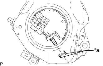
Text in Illustration *a Matchmark Install the urea pump to the urea tank sub-assembly as shown in the illustration.
-
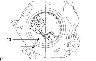
Text in Illustration *a Co-rotation Prevention Check Mark Apply a co-rotation prevention check mark to the urea pump and urea tank sub-assembly.
Tech Tips
Perform this procedure when replacement of the urea pump is necessary.
-
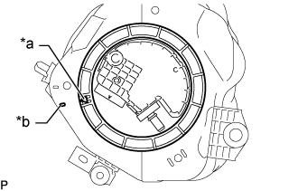
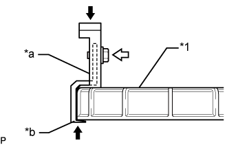
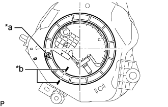
Text in Illustration *a Rotational Start Point Mark
(Urea Pump Gauge Retainer Side)
*b Rotational Start Point Mark
(Urea Tank Sub-assembly Side)
Temporarily place the urea pump gauge retainer by aligning the rotational start point mark of the urea urea pump gauge retainer with the rotational start point mark of the urea tank sub-assembly while pressing the urea pump into the urea tank assembly.
-
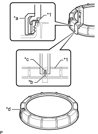
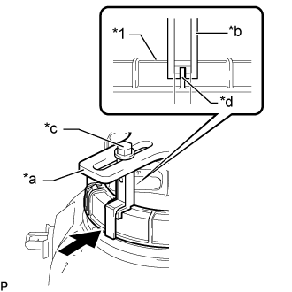
Text in Illustration *1 Urea Pump Gauge Retainer *a SST (Claw Set) *b Rib *c Cutout *d SST (Claw Set) Incorrect Installation Point (Rotational Start Point Mark of Urea pump Gauge Retainer) Set 4 SSTs (claw sets) to the urea pump gauge retainer and temporarily install.
- SST
- 09808-14031 ( 09808-01080, 09808-01090, 09808-01100 )
-
Text in Illustration *1 Urea Pump Gauge Retainer *a SST (Claw Set) *b Press 
Pinch 
SST (Bolt) While firmly pressing the claw of SST into rib of the urea pump gauge retainer, tighten the bolt.
-
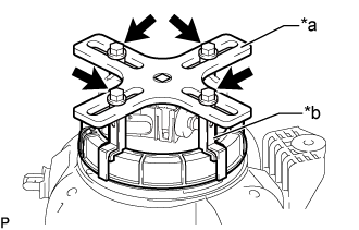
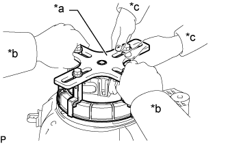
Text in Illustration *a SST (Plate) *b SST (Claw Set) SST (Bolt) Temporarily install SST (plate) to SST (claw set) with 4 SSTs (bolts).
-
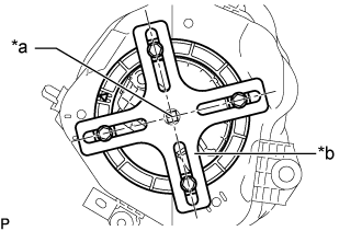
Text in Illustration *a Center of Urea Pump Gauge Retainer *b SST (Plate) Adjust the position of SST (plate) so that the setting hole of SST (handle) aligns with the center of the urea pump gauge retainer.
-
Text in Illustration *1 Urea Pump Gauge Retainer *a SST (Plate) *b SST (Claw Set) *c SST (Bolt) *d Rib Press While firmly pressing SST (claw set) into rib of the urea pump gauge retainer, tighten SST (bolt).
-
Text in Illustration *a Tighten Start Position *b Co-rotation Prevention Check Mark While one person presses the urea pump into the urea tank sub-assembly, have another person firmly press the urea pump gauge retainer into the threads of the urea tank assembly and tighten approximately one and a half turns.
Note
-
Do not any tools other than SST, such as a screwdriver, etc.
-
Do not excessive force when pressing down on SST, as the urea pump will place excessive force on urea pump gauge retainer and be difficult to remove, and parts may be damaged.
-
Do not use an impact wrench or turn SST handle with excessive force, as parts may be damaged.
-
Do not rotate the urea pump gauge retainer when the co-rotation prevention check mark is out of place.
-
-
Text in Illustration *a SST (Plate) *b Person in Change of Tightening *c Person in Charge of Supporting While one person presses the urea pump into the urea tank sub-assembly have another person slowly tighten approximately half turns.
-
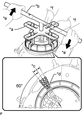
Text in Illustration *a SST (Plate) *b SST (Handle) *c Tightening Complete Position *d Rotational Start Point Mark of Urea Pump Gauge Retainer *e Person in Charge of Tightening *f Person in Charge of Supporting Tighten Install SST (handle) to SST (plate).
- SST
- 09808-14031 ( 09808-01010, 09808-01020 )
-
While one person presses the urea pump onto the urea tank sub-assembly, have another person use SST (handle) and slowly tighten the urea pump gauge retainer until it reaches the tightening complete position.
-
-
INSTALL UREA TANK SUB-ASSEMBLY