DYNAMIC RADAR CRUISE CONTROL SYSTEM Millimeter Wave Radar Sensor Power Source Circuit
| DTC Code | DTC Name |
|---|---|
| Millimeter Wave Radar Sensor Power Source Circuit |
DESCRIPTION
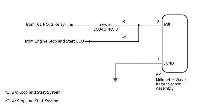
When the ignition switch is turned to ON, battery voltage is applied to terminal IGB of the millimeter wave radar sensor assembly.
This circuit provides power to the millimeter wave radar sensor assembly. The millimeter wave radar sensor assembly emits radio waves towards an object in front and measures the distance and direction of the object by receiving the beam reflections. Based on the reflections, the sensor calculates the difference in speed between the vehicle and the object in front. This data is transmitted to the driving support ECU assembly.
WIRING DIAGRAM
CAUTION / NOTICE / HINT
Inspect the fuses for circuits related to this system before performing the following inspection procedure.
PROCEDURE
CHECK MILLIMETER WAVE RADAR SENSOR ASSEMBLY (IGB VOLTAGE)
-
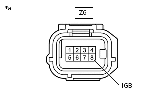
*a
Front view of wire harness connector
(to Millimeter Wave Radar Sensor Assembly)
Disconnect the Z6 millimeter wave radar sensor assembly connector.
Turn the ignition switch to ON.
Measure the voltage according to the value(s) in the table below.
Standard Voltage
Tester Connection
Switch Condition
Specified Condition
Z6-8 (IGB) - Bodyground
Ignition switch ON
11 to 14 V*1
10.5 to 16 V*2
*1: w/o Stop and Start System
*2: w/ Stop and Start System
Reconnect the Z6 millimeter wave radar sensor assembly connector.
Result
Proceed to
OK
NG
NG REPAIR OR REPLACE POWER SOURCE CIRCUIT
-
CHECK HARNESS AND CONNECTOR (MILLIMETER WAVE RADAR SENSOR ASSEMBLY - BODY GROUND)
Disconnect the Z6 millimeter wave radar sensor assembly connector.
Measure the resistance according to the value(s) in the table below.
Standard Resistance
Check for Open
Tester Connection
Condition
Specified Condition
Z6-1 (SGND) - Body ground
Always
Below 1 Ω
Reconnect the Z6 millimeter wave radar sensor assembly connector.
Result
Proceed to
OK
NG
NG REPAIR OR REPLACE HARNESS OR CONNECTOR