INTAKE MANIFOLD INSTALLATION
PROCEDURE
INSTALL INTAKE AIR CONTROL VALVE ACTUATOR (for TCV)
INSTALL PURGE LINE HOSE
Install the purge line hose to the intake manifold, and slide the clamp to secure it.
Connect the purge line hose to the clamp.
INSTALL CHECK VALVE
Install the 2 vacuum hoses to the check valve.
Connect the 2 vacuum hoses to the intake manifold to install the check valve.
-
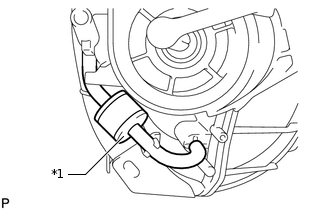
*1
Black
Check that the check valve is installed as shown in the illustration.
INSTALL UNION TO CONNECTOR TUBE HOSE
Install the union to connector tube hose to the intake manifold, and slide the clamp to secure it.
INSTALL INTAKE MANIFOLD
Install the 2 vacuum hoses to the intake manifold.
-
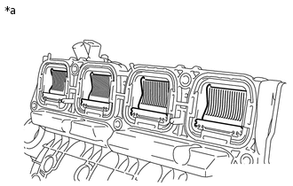
*a
Condition: Closed
for TCV:
Close the tumble control valves.
Note:The valves may be damaged if they are not closed before installing the intake manifold.
Tip:Connect the battery to the terminals of the actuator and operate the motor to close the valves.
-
Install a new gasket to the intake manifold.
-
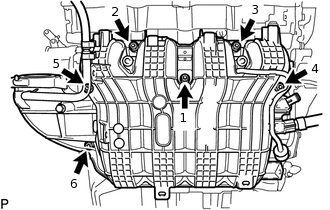
Install the intake manifold with the 6 bolts and tighten the bolts in the sequence shown in the illustration.
28 N*m
286 kgf*cm
21 ft.*lbf
CONNECT NO. 2 PCV HOSE
Connect the No. 2 PCV hose to the intake manifold, and slide the clamp to secure it.
CONNECT WIRE HARNESS
Attach the clamp and connect the wire harness.
Install the bracket with the bolt.
10 N*m
102 kgf*cm
7 ft.*lbf
for TCV:
Connect the intake air control actuator connector.
Install the wire harness clamp bracket with the 2 bolts.
10 N*m
102 kgf*cm
7 ft.*lbf
Attach the 2 clamps.
Connect the 2 vacuum hoses and connector and attach the clamp to the vacuum switching valve.
CONNECT HEATER HOSE
Connect the outlet heater water hose to the heater radiator unit, and slide the clamp to secure the hose.
Connect the inlet heater water hose to the heater radiator unit, and slide the clamp to secure the hose.
INSTALL NO. 1 HOSE TO HOSE TUBE
Install the No. 1 hose to hose tube with the 2 nuts.
5.4 N*m
55 kgf*cm
48 in.*lbf
Connect the 2 hoses, and slide the 2 clamps to secure the hoses.
INSTALL OUTER COWL TOP PANEL SUB-ASSEMBLY
Install the outer cowl top panel sub-assembly with the 13 bolts.
7.0 N*m
71 kgf*cm
62 in.*lbf
Attach the clamp to the outer cowl top panel sub-assembly.
INSTALL WINDSHIELD WIPER MOTOR ASSEMBLY
INSTALL THROTTLE WITH MOTOR BODY ASSEMBLY
INSTALL FUEL DELIVERY PIPE
ADD ENGINE COOLANT
INSPECT FOR COOLANT LEAK