REAR AXLE BEAM INSTALLATION

PROCEDURE
-
INSTALL REAR AXLE CARRIER BUSHING LH
-
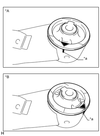
Text in Illustration *A for Type A *B for Type B *a Matchmark Align the arrow mark on a new rear axle carrier bushing LH with the matchmark on the rear axle beam assembly and temporarily install the rear axle carrier bushing LH to the rear axle beam assembly. (If the rear axle beam assembly is reused.)
Note
There are 2 different types of rear axle carrier bushing LH. Be sure to confirm the type and install the bushing in the correct direction as shown in the illustration.
-
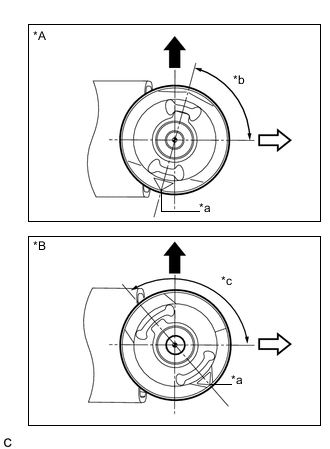
Text in Illustration *A for Type A *B for Type B *a Mark *b 75° *c 135° 
Upper Side of the Vehicle 
Front of the Vehicle Temporarily install the new rear axle carrier bushing LH as shown in the illustration.
Note
There are 2 different types of rear axle carrier bushing LH. Be sure to confirm the type and install the bushing in the correct direction as shown in the illustration.
-
Using SST, install the rear axle carrier bushing LH to the rear axle beam assembly.
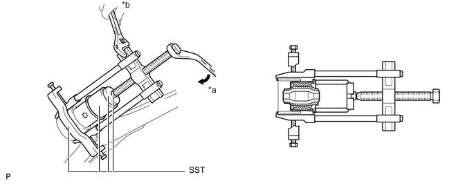
Text in Illustration *a Turn *b Hold - SST
- 09710-30012 ( 09710-04101 )
- 09950-40011 ( 09951-04020, 09952-04010, 09953-04030, 09954-04020, 09955-04051, 09957-04010, 09958-04011 )
- 09950-60010 ( 09951-00620 )
Note
-
Do not damage the rubber portion when installing the rear axle carrier bushing.
-
Apply grease to the threads and tip of the SST center bolt before use.
-
-
INSTALL REAR AXLE CARRIER BUSHING RH
Tech Tips
Perform the same procedure as for the LH side.
-
TEMPORARILY TIGHTEN REAR AXLE BEAM ASSEMBLY
-
Slowly jack up the rear axle beam assembly with an engine lifter using 2 wooden blocks and 2 attachments or equivalent tools and temporarily install the rear axle beam assembly to the body with the 2 bolts (B).
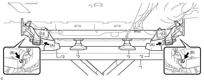
Text in Illustration *1 Engine Lifter *2 Wooden Block *3 Attachment - - Note
Make sure to secure the rear axle beam assembly to prevent it from dropping.
-
Temporarily tighten the rear axle beam assembly to the rear shock absorber assemblies LH and RH with the 2 bolts (A) and 2 nuts.
Note
Since the stopper nuts are used, turn the bolts.
Tech Tips
Insert the bolts with the threaded end facing the outside of the vehicle.
-
-
INSTALL REAR UPPER COIL SPRING INSULATOR LH
-
INSTALL REAR UPPER COIL SPRING INSULATOR RH
Tech Tips
Perform the same procedure as for the LH side.
-
INSTALL REAR LOWER COIL SPRING INSULATOR LH
-
INSTALL REAR LOWER COIL SPRING INSULATOR RH
-
INSTALL REAR COIL SPRING LH
-
INSTALL REAR COIL SPRING RH
Tech Tips
Perform the same procedure as for the LH side.
-
INSTALL REAR HEIGHT CONTROL SENSOR SUB-ASSEMBLY (w/ Height Control Sensor)
-
TEMPORARILY TIGHTEN PARKING BRAKE ASSEMBLY (for LH Side)
-
Clean the installation surfaces of the parking brake assembly and rear axle beam assembly.
-
Temporarily tighten the parking brake assembly to the rear axle beam assembly with the nut.
Note
Do not twist the No. 3 parking brake cable assembly when installing the parking brake assembly.
Tech Tips
Fully tighten the nut after installing the rear axle hub and bearing assembly.
-
Install the No. 3 parking brake cable assembly to the rear axle beam assembly with the bolt.
- Torque:
- 6.0 N*m { 61 kgf*cm, 53 in.*lbf }
-
-
TEMPORARILY TIGHTEN PARKING BRAKE ASSEMBLY (for RH Side)
Tech Tips
Perform the same procedure as for the LH side.
-
INSTALL REAR AXLE HUB AND BEARING ASSEMBLY LH
-
INSTALL REAR AXLE HUB AND BEARING ASSEMBLY RH
Tech Tips
Perform the same procedure as for the LH side.
-
FULLY TIGHTEN PARKING BRAKE ASSEMBLY (for LH Side)
-
Fully tighten the nut.
- Torque:
- 140 N*m { 1428 kgf*cm, 103 ft.*lbf }
-
-
FULLY TIGHTEN PARKING BRAKE ASSEMBLY (for RH Side)
Tech Tips
Perform the same procedure as for the LH side.
-
INSTALL REAR NO. 4 BRAKE TUBE
-
Install the rear No. 4 brake tube to the rear axle beam assembly with the nut.
- Torque:
- 8.5 N*m { 87 kgf*cm, 75 in.*lbf }
-
-
INSTALL REAR NO. 3 BRAKE TUBE
Tech Tips
Perform the same procedure as for the rear No. 4 brake tube.
-
CONNECT REAR BRAKE TUBE FLEXIBLE HOSE (for LH Side)
-
Install the rear brake tube flexible hose with the bolt.
- Torque:
- 19 N*m { 194 kgf*cm, 14 ft.*lbf }
-
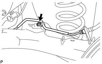
Using a union nut wrench, connect the rear brake tube flexible hose to the rear No. 4 brake tube.
- Torque:
- 15 N*m { 155 kgf*cm, 11 ft.*lbf }
Note
-
Do not bend or damage the brake line.
-
Do not allow any foreign matter such as dirt and dust to enter the brake line from the connecting points.
-
Use the formula to calculate special torque values for situations where the union nut wrench is combined with a torque wrench Click here.
-
-
CONNECT REAR BRAKE TUBE FLEXIBLE HOSE (for RH Side)
-
Install the rear brake tube flexible hose with a new clip.
Note
Install the clip as far as it will go.
-
Using a union nut wrench, connect the rear brake tube flexible hose to the rear No. 3 brake tube.
- Torque:
- 15 N*m { 155 kgf*cm, 11 ft.*lbf }
Note
-
Do not bend or damage the brake line.
-
Do not allow any foreign matter such as dirt and dust to enter the brake line from the connecting points.
-
Use the formula to calculate special torque values for situations where the union nut wrench is combined with a torque wrench Click here.
-
-
INSTALL REAR DISC (for LH Side)
-
INSTALL REAR DISC (for RH Side)
Tech Tips
Perform the same procedure as for the LH side.
-
INSTALL PARKING BRAKE SHOE ADJUSTING HOLE PLUG
-
Install the 2 parking brake shoe adjusting hole plugs.
-
-
INSTALL REAR DISC BRAKE CALIPER ASSEMBLY LH
-
Install the rear disc brake caliper assembly LH with rear flexible hose LH with the 2 bolts.
- Torque:
- 72 N*m { 734 kgf*cm, 53 ft.*lbf }
-
Connect the rear flexible hose LH to the rear axle beam assembly with a new clip.
Note
Install the clip as far as it will go.
-
Using a union nut wrench, connect the rear No. 4 brake tube to the rear flexible hose LH while holding the rear flexible hose LH with a wrench.
- Torque:
- 15 N*m { 155 kgf*cm, 11 ft.*lbf }
Note
-
Do not bend or damage the brake line.
-
Do not allow any foreign matter such as dirt and dust to enter the brake line from the connecting points.
-
Use the formula to calculate special torque values for situations where the union nut wrench is combined with a torque wrench Click here.
-
-
INSTALL REAR DISC BRAKE CALIPER ASSEMBLY RH
Tech Tips
Perform the same procedure as for the LH side.
-
INSTALL SKID CONTROL SENSOR WIRE LH
-
INSTALL SKID CONTROL SENSOR WIRE RH
Tech Tips
Perform the same procedure as for the LH side.
-
CONNECT SKID CONTROL SENSOR WIRE LH
-
CONNECT SKID CONTROL SENSOR WIRE RH
Tech Tips
Perform the same procedure as for the LH side.
-
INSTALL REAR SUSPENSION BRACE SUB-ASSEMBLY
-
Install the rear suspension brace sub-assembly with the 4 bolts.
- Torque:
- 54 N*m { 551 kgf*cm, 40 ft.*lbf }
-
-
FILL RESERVOIR WITH BRAKE FLUID
-
CONNECT CABLE TO NEGATIVE AUXILIARY BATTERY TERMINAL
-
Connect the cable to the negative (-) auxiliary battery terminal Click here.
-
-
BLEED BRAKE LINE
-
INSTALL REAR FLOOR SIDE MEMBER COVER RH
-
Engage the 3 clips to temporarily install the rear floor side member cover RH.
-
Install the rear floor side member cover RH with the 3 bolts.
-
-
ADJUST PARKING BRAKE
-
INSTALL REAR WHEELS
- Torque:
- 103 N*m { 1050 kgf*cm, 76 ft.*lbf }
-
STABILIZE SUSPENSION
-
FULLY TIGHTEN REAR AXLE BEAM ASSEMBLY
-
INSTALL REAR WHEEL HOUSE LINER LH
-
INSTALL REAR WHEEL HOUSE LINER RH
Tech Tips
Perform the same procedure as for the LH side.
-
INSPECT REAR WHEEL ALIGNMENT
-
PLACE FRONT WHEELS FACING STRAIGHT AHEAD
-
PERFORM YAW RATE AND ACCELERATION SENSOR CALIBRATION
-
CHECK FOR SPEED SENSOR SIGNAL
-
INITIALIZE HEIGHT CONTROL SENSOR SIGNAL (w/ Height Control Sensor)
-
ADJUST HEADLIGHT AIMING (w/ Height Control Sensor)