FRONT CONSOLE BOX(for Sedan) REMOVAL
PROCEDURE
REMOVE LOWER NO. 2 INSTRUMENT PANEL FINISH PANEL
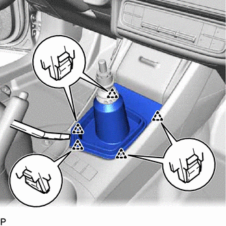
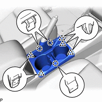
REMOVE FRONT NO. 1 CONSOLE BOX INSERT
-
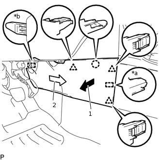
*a
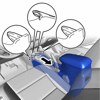
Guide <A>
*b
Guide <B>
Pull the front No. 1 console box insert in the direction indicated by the arrow (1) to disengage the claw, 3 clips and guide <A>.
Pull the front No. 1 console box insert in the direction indicated by the arrow (2) to disengage the guide <B> and remove the front No. 1 console box insert.
-
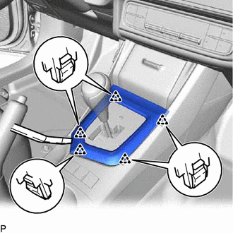
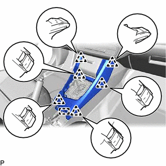
REMOVE FRONT NO. 2 CONSOLE BOX INSERT
-
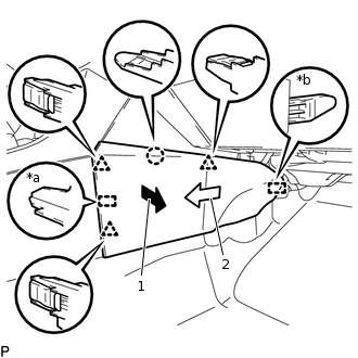
*a
Guide <A>
*b
Guide <B>
Pull the front No. 2 console box insert in the direction indicated by the arrow (1) to disengage the claw, 3 clips and guide <A>.
Pull the front No. 2 console box insert in the direction indicated by the arrow (2) to disengage the guide <B> and remove the front No. 2 console box insert.
-
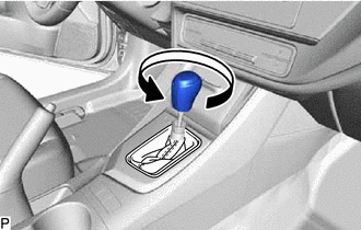
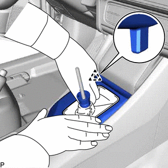
REMOVE SHIFT LEVER KNOB SUB-ASSEMBLY
-
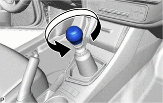
for Manual Transaxle:
Turn the shift lever knob sub-assembly counterclockwise and remove the shift lever knob sub-assembly.
for CVT:
-
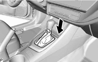
Disengage the claw to disconnect the position indicator housing assembly as shown in the illustration.
-
Turn the shift lever knob sub-assembly counterclockwise and remove the shift lever knob sub-assembly.
-
-
REMOVE SHIFTING HOLE BEZEL
for Manual Transaxle:
-
Using a moulding remover, disengage the 5 clips and remove the shifting hole bezel.
-
for Multi-Mode Manual Transaxle:
-
Using a moulding remover, disengage the 5 clips and remove the shifting hole bezel.
-
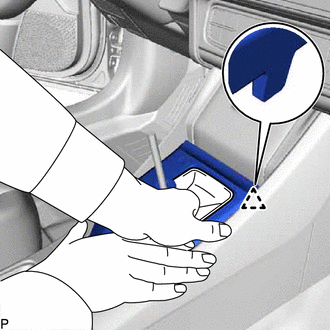
REMOVE POSITION INDICATOR HOUSING ASSEMBLY (for CVT)
-
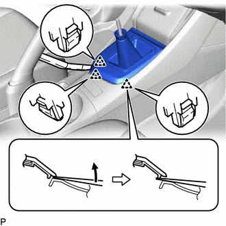
Using a moulding remover as shown in the illustration, disengage the 3 clips.
-
Disengage the clip as shown in the illustration.
-
Disengage the clip as shown in the illustration.
Disconnect the connector to remove the position indicator housing assembly.
-
REMOVE UPPER CONSOLE PANEL SUB-ASSEMBLY
-
Disengage the 3 claws and 5 clips and remove the upper console panel sub-assembly.
-
REMOVE UPPER CONSOLE PANEL
-
Disengage the 6 clips.
Disengage the clamp.
Disconnect each connector to remove the upper console panel.
-
REMOVE INSTRUMENT PANEL BOX ASSEMBLY
-
Disengage the 4 clips.
Disconnect each connector.
Disengage the clamp to remove the instrument panel box assembly.
-
REMOVE CONSOLE BOX CARPET
-
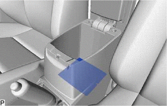
Remove the console box carpet.
-
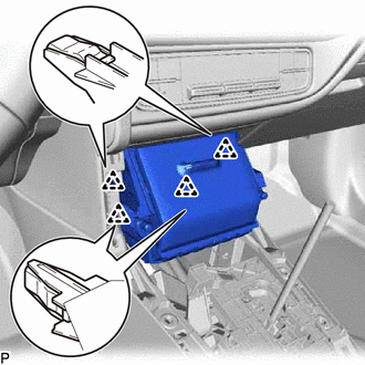
REMOVE REAR CONSOLE BOX ASSEMBLY
for Manual Transaxle:
-
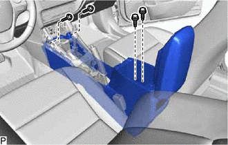
Remove the 2 bolts and 2 screws.
-
except Manual Transaxle:
-
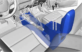
Remove the 2 bolts and 4 screws.
-
-
Disengage the 4 guides and remove the rear console box assembly as shown in the illustration.
w/ Power Outlet Socket:
Disconnect the connector.