LIGHTING SYSTEM Footwell Light Circuit
| DTC Code | DTC Name |
|---|---|
| Footwell Light Circuit |
DESCRIPTION
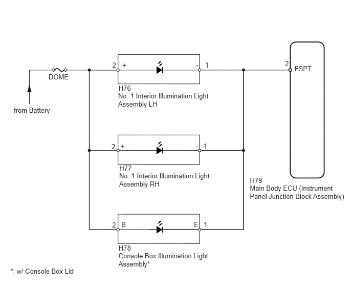
The main body ECU receives information regarding the door lock position switch and ignition switch, and turns on each No. 1 interior illumination light and the console box illumination light*.
*: w/ Console Box Lid
WIRING DIAGRAM
CAUTION / NOTICE / HINT
Inspect the fuses for circuits related to this system before performing the following inspection procedure.
PROCEDURE
PERFORM ACTIVE TEST USING INTELLIGENT TESTER (MAIN BODY ECU)
*: w/ Console Box Lid
Connect the intelligent tester to the DLC3.
Turn the ignition switch to ON.
Turn the intelligent tester on.
Turn the map light switch to the DOOR position.
Enter the following menus: Body / Main Body / Active Test / Step light Operation.
Use the Active Test to check the operation of the No. 1 interior illumination lights and console box illumination light*.
Table 1. Main Body Tester Display
Test Part
Control Range
Diagnostic Note
Step light Operation
No. 1 interior illumination lights and console box illumination light*
ON/OFF
-
OK
No. 1 interior illumination lights and console box illumination light* come on.
Table 2. Result Result
Proceed to
OK
A
NG (No. 1 interior illumination lights do not come on)
B
NG (Console box illumination light does not come on)*
C
INSPECT CONSOLE BOX ILLUMINATION LIGHT ASSEMBLYClick here
INSPECT NO. 1 INTERIOR ILLUMINATION LIGHT ASSEMBLY
-
Remove the No. 1 interior illumination light LH (Click here).
Remove the No. 1 interior illumination light RH (Click here).
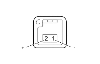
Connect the positive (+) lead from the battery to terminal 2 and the negative (-) lead to terminal 1, and check that the light comes on.
OK
Light comes on.
Table 3. Result Result
Proceed to
OK
A
NG (for LH)
B
NG (for RH)
C
-
CHECK HARNESS OR CONNECTOR (NO. 1 INTERIOR ILLUMINATION LIGHT ASSEMBLY - MAIN BODY ECU AND BATTERY)
-
Disconnect the H79 main body ECU connector.
Disconnect the H76*1 or H77*2 No. 1 interior illumination light connector.
*1: for LH
*2: for RH
Measure the voltage and resistance according to the value(s) in the table below.
Standard Voltage
for LH
Tester Connection
Condition
Specified Condition
H76-2 (+) - Body ground
Always
11 to 14 V
for RH
Tester Connection
Condition
Specified Condition
H77-2 (+) - Body ground
Always
11 to 14 V
Standard Resistance
for LH
Tester Connection
Condition
Specified Condition
H76-1 (-) - H79-2 (FSPT)
Always
Below 1 Ω
H76-1 (-) - Body ground
Always
10 kΩ or higher
for RH
Tester Connection
Condition
Specified Condition
H77-1 (-) - H79-2 (FSPT)
Always
Below 1 Ω
H77-1 (-) - Body ground
Always
10 kΩ or higher
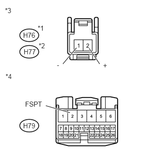
Table 4. Text in Illustration *1
for LH
*2
for RH
*3
Front view of wire harness connector
(to No. 1 Interior Illumination Light Assembly)
*4
Front view of wire harness connector
(to Main Body ECU)
REPLACE MAIN BODY ECU (INSTRUMENT PANEL JUNCTION BLOCK ASSEMBLY)
REPAIR OR REPLACE HARNESS OR CONNECTOR
-
INSPECT CONSOLE BOX ILLUMINATION LIGHT ASSEMBLY
-
Remove the console box illumination light (Click here).
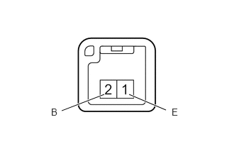
Connect the positive (+) lead from the battery to terminal 2 and the negative (-) lead to terminal 1, and check that the light comes on.
OK
Light comes on.
-
CHECK HARNESS OR CONNECTOR (CONSOLE BOX ILLUMINATION LIGHT ASSEMBLY - MAIN BODY ECU AND BATTERY)
-
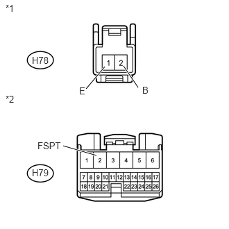
Disconnect the H79 main body ECU connector.
Disconnect the H78 console box interior illumination light connector.
Measure the voltage and resistance according to the value(s) in the table below.
Standard Voltage
Tester Connection
Condition
Specified Condition
H78-2 (B) - Body ground
Always
11 to 14 V
Standard Resistance
Tester Connection
Condition
Specified Condition
H78-1 (E) - H79-2 (FSPT)
Always
Below 1 Ω
H78-1 (E) - Body ground
Always
10 kΩ or higher
Table 5. Text in Illustration *1
Front view of wire harness connector
(to Console Box Illumination Light Assembly)
*2
Front view of wire harness connector
(to Main Body ECU)
REPLACE MAIN BODY ECU (INSTRUMENT PANEL JUNCTION BLOCK ASSEMBLY)
REPAIR OR REPLACE HARNESS OR CONNECTOR
-