SFI SYSTEM, Diagnostic DTC:P0121 and P0221
| DTC Code | DTC Name |
|---|---|
| P0121 | Throttle / Pedal Position Sensor / Switch "A" Circuit Range / Performance |
| P0221 | Throttle / Pedal Position Sensor / Switch "B" Circuit Range / Performance Problem |
DESCRIPTION
This ETCS (Electrical Throttle Control System) does not use a throttle cable.
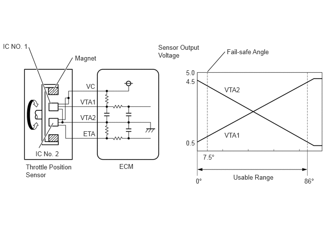
The throttle position sensor is mounted on the throttle body with motor assembly, and detects the opening angle of the throttle valve.
The throttle body with motor assembly sensor has 2 sensor circuits which each transmits a signal, VTA1 and VTA2. VTA1 is used to detect the throttle valve angle and VTA2 is used to detect malfunctions in VTA1. The sensor signal voltages vary between 0 V and 5 V. The VTA1 sensor signal voltage varies in proportion to the throttle valve opening angle, and is transmitted to the VTA1 terminals of the ECM.
As the valve closes, the VTA1 sensor output voltage decreases, and as the valve opens, the VTA1 sensor output voltage increases. The ECM calculates the throttle valve opening angle according to these signals and controls the throttle actuator in response to driver inputs.
DTC No. |
Detection Item |
DTC Detection Condition |
Trouble Area |
MIL |
Memory |
|---|---|---|---|---|---|
P0121 |
Throttle / Pedal Position Sensor / Switch "A" Circuit Range / Performance |
Both of the following conditions are met for 0.4 seconds (1 trip detection logic):
|
|
Comes on |
DTC stored |
P0221 |
Throttle / Pedal Position Sensor / Switch "B" Circuit Range / Performance Problem |
Both of the following conditions are met for 0.4 seconds (1 trip detection logic):
|
|
Comes on |
DTC stored |
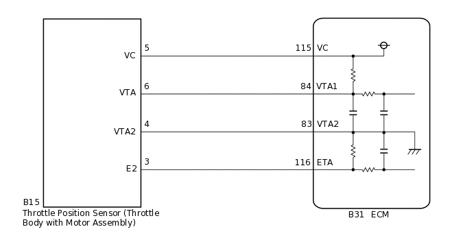
WIRING DIAGRAM
CONFIRMATION DRIVING PATTERN
When performing the confirmation driving pattern, obey all speed limits and traffic laws.
DTC P0121 and P0221 are detected when the vehicle is driven in the city at 30 to 50 km/h (19 to 31 mph) for 5 minutes.
CAUTION / NOTICE / HINT
After replacing the ECM and/or throttle body with motor assembly, perform electronic throttle learning and idle learning.
If any DTCs related to the crankshaft position sensor sensor, throttle position sensor and accelerator pedal sensor assembly are output simultaneously, inspect the VC circuit of each component.
Read freeze frame data using the GTS. Freeze frame data records the engine condition when malfunctions are detected. When troubleshooting, freeze frame data can help determine if the vehicle was moving or stationary, if the engine was warmed up or not, if the air fuel ratio was lean or rich, and other data from the time the malfunction occurred.
PROCEDURE
READ VALUE USING GTS (THROTTLE POSITION SENSOR)
Connect the GTS to the DLC3.
Turn the ignition switch to ON.
Turn the GTS on.
Enter the following menus: Powertrain / Engine and ECT / Data List / All Data / Throttle Position No.1 and Throttle Position No.2.
Powertrain > Engine and ECT > Data List
Tester Display
Throttle Position No.1
Throttle Position No.2
Read the values displayed on the GTS.
Result
When Accelerator Pedal Fully Released
When Accelerator Pedal Fully Depressed
Trouble Area
Proceed to
Throttle Position No.1 (VTA1)
Throttle Position No.2 (VTA2)
Throttle Position No.1 (VTA1)
Throttle Position No.2 (VTA2)
4.8 to 4.98 V
0 to 0.2 V
4.8 to 4.98 V
0 to 0.2 V
VC circuit open
A
4.5 to 4.98 V
0 to 0.2 V
4.8 to 4.98 V
0 to 0.2 V
ETA circuit open
0 to 0.2 V, or 4.8 to 4.98 V
3.9 to 4.4 V
0 to 0.2 V, or 4.8 to 4.98 V
3.9 to 4.3 V
VTA1 circuit open or shorted to ground
0.6 to 1.1 V
0 to 0.2 V, or 4.8 to 4.98 V
0.7 to 1.1 V
0 to 0.2 V, or 4.8 to 4.98 V
VTA2 circuit open or shorted to ground
0.6 to 1.1 V
3.9 to 4.4 V
4.2 to 4.54 V
0.46 to 0.76 V
Throttle position sensor circuit normal
B
B CHECK WHETHER DTC OUTPUT RECURS (DTC P0121 OR P0221)Click here
CHECK HARNESS AND CONNECTOR (THROTTLE BODY WITH MOTOR ASSEMBLY - ECM)
Disconnect the throttle body with motor assembly connector.
Disconnect the ECM connector.
Measure the resistance according to the value(s) in the table below.
Standard Resistance
Tester Connection
Condition
Specified Condition
B15-5 (VC) - B31-115 (VC)
Always
Below 1 Ω
B15-6 (VTA) - B31-84 (VTA1)
Always
Below 1 Ω
B15-4 (VTA2) - B31-83 (VTA2)
Always
Below 1 Ω
B15-3 (E2) - B31-116 (ETA)
Always
Below 1 Ω
B15-5 (VC) or B31-115 (VC) - Body ground
Always
10 kΩ or higher
B15-6 (VTA) or B31-84 (VTA1) - Body ground
Always
10 kΩ or higher
B15-4 (VTA2) or B31-83 (VTA2) - Body ground
Always
10 kΩ or higher
B15-3 (E2) or B31-116 (ETA) - Body ground
Always
10 kΩ or higher
Result
Proceed to
OK
NG
NG REPAIR OR REPLACE HARNESS OR CONNECTOR
REPLACE THROTTLE BODY WITH MOTOR ASSEMBLY
Replace the throttle body with motor assembly.
Perform electronic throttle learning and idle learning.
Result
Proceed to
NEXT
CHECK WHETHER DTC OUTPUT RECURS (DTC P0121 OR P0221)
Connect the GTS to the DLC3.
Turn the ignition switch to ON.
Turn the GTS on.
Clear the DTCs.
Powertrain > Engine and ECT > Clear DTCs
Turn the ignition switch off and wait for at least 30 seconds.
Start the engine.
Turn the GTS on.
Drive the vehicle at between 30 to 50 km/h (19 to 31 mph) for 5 minutes.
Enter the following menus: Powertrain / Engine and ECT / Trouble Codes.
Read the DTCs.
Powertrain > Engine and ECT > Trouble Codes
OK
DTCs are not output.
Result
Proceed to
OK
NG
OK END