СИСТЕМА МЕХАНИЧЕСКОЙ ТРАНСМИССИИ Pattern Select Switch iMT Mode Circuit
DESCRIPTION
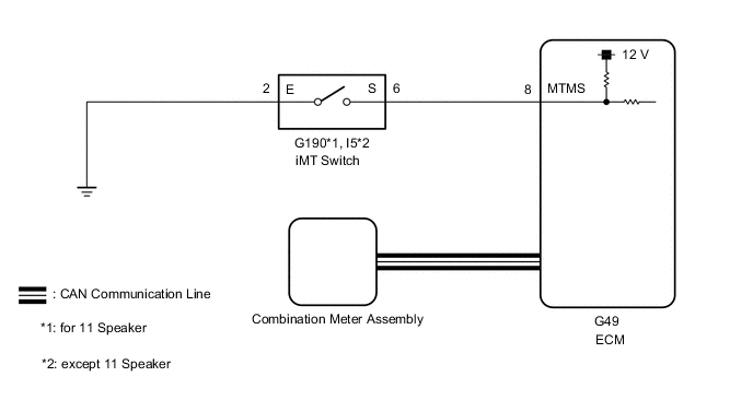
Operating the iMT switch illuminates the iMT indicator light in the combination meter. This displays the iMT system standby condition.
WIRING DIAGRAM
PROCEDURE
-
READ VALUE USING GTS (IMT SWITCH)
-
Connect the GTS to the DLC3.
-
Turn the ignition switch to ON.
-
Turn the GTS on.
-
Enter the following menus: Powertrain / Engine and ECT / Data List
-
According to the display on the GTS, read the Data List.
Powertrain > Engine and ECT > Data ListTester Display Measurement Item Range Normal Condition Diagnostic Note iMT Switch iMT switch status ON or OFF
-
ON: iMT switch being pressed and held
-
OFF: iMT switch not pressed
-
Powertrain > Engine and ECT > Data ListTester Display iMT Switch Result Result Proceed to Data display is within Normal Condition range A Data display is not within Normal Condition range B -
A 
PROCEED TO NEXT SUSPECTED AREA SHOWN IN PROBLEM SYMPTOMS TABLE Click here
B 
-
-
CHECK HARNESS AND CONNECTOR (IMT SWITCH - BODY GROUND)
-
Disconnect the transmission revolution sensor connector.
-
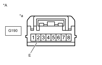
*A for 11 Speaker *a Front view of wire harness connector
(to iMT Switch)
for 11 Speaker:
Measure the resistance according to the value(s) in the table below.
Standard Resistance Tester Connection Condition Specified Condition G190-2 (E) - Body ground Always Below 1 Ω -
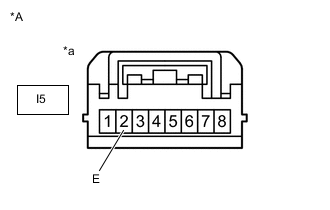
*A except 11 Speaker *a Front view of wire harness connector
(to iMT Switch)
except 11 Speaker:
Measure the resistance according to the value(s) in the table below.
Standard Resistance Tester Connection Condition Specified Condition I5-2 (E) - Body ground Always Below 1 Ω Result Proceed to OK NG
NG
REPAIR OR REPLACE HARNESS OR CONNECTOR
OK
-
-
CHECK HARNESS AND CONNECTOR (IMT SWITCH - ECM)
-
Disconnect the iMT switch connector.
-
Disconnect the ECM connector.
-
Measure the resistance according to the value(s) in the table below.
Standard Resistance for 11 Speaker Tester Connection Condition Specified Condition G190-6 (S) - G49-8 (MTMS) Always Below 1 Ω G190-6 (S) - Body ground Always 10 kΩ or higher except 11 Speaker Tester Connection Condition Specified Condition I5-6 (S) - G49-8 (MTMS) Always Below 1 Ω I5-6 (S) - Body ground Always 10 kΩ or higher Result Proceed to OK NG
NG
REPAIR OR REPLACE HARNESS OR CONNECTOR
OK
-
-
INSPECT IMT SWITCH
-
Inspect the iMT switch.
Result Proceed to OK NG
OK
PROCEED TO NEXT SUSPECTED AREA SHOWN IN PROBLEM SYMPTOMS TABLE Click here
NG
REPLACE IMT SWITCH (COMBINATION SWITCH ASSEMBLY) Click here
-